English-2
• Mount the drive upright on a flat, vertical and level surface.
• Protect the cooling fan by avoiding dust or metallic particles.
• Do not expose to a corrosive atmosphere.
• Protect from moisture and direct sunlight.
Minimum Mounting Clearances
Ambient Operating Temperatures
Refer to the PowerFlex 40 User Manual on the CD supplied with the
drive for details on how to comply with the Low Voltage (LV) and
Electromagnetic Compatibility (EMC) Directives.
Mounting Considerations
Frame Screw Size Screw Torque DIN Rail
B M4 (#8-32) 1.56-1.96 N-m (14-17 lb.-in.) 35 mm
C M5 (#10-24) 2.45-2.94 N-m (22-26 lb.-in.) –
Ambient Temperature Enclosure Rating Minimum Mounting
Clearances
Minimum Maximum
-10°C (14°F)
40°C (104°F)
IP 20/Open Type Use Mounting Option A
IP 30/NEMA 1/UL Type 1
(1)
(1)
Rating requires installation of the PowerFlex 40 IP 30/NEMA 1/UL Type 1 option kit.
Use Mounting Option B
50°C (122°F) IP 20/Open Type Use Mounting Option B
25 mm
(1.0 in.)
120 mm
(4.7 in.)
120 mm
(4.7 in.)
120 mm
(4.7 in.)
120 mm
(4.7 in.)
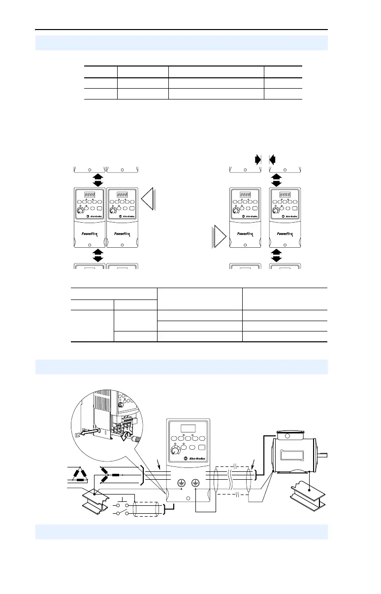
Mounting Option A
No clearance required
between drives.
Mounting Option B
See page 16 for mounting dimensions.
General Grounding Requirements
U/T1
V/T2
W/T3
R/L1
S/L2
T/L3
SHLD
Important: The MOV to ground jumper must be
removed if the drive is installed on an ungrounded or
resistive grounded distribution system.
Tighten screw after jumper removal.
Jumper
Location
CE Conformity

 Loading...


