14
Jul. 2007 AC-90
Verifying the Version
Number
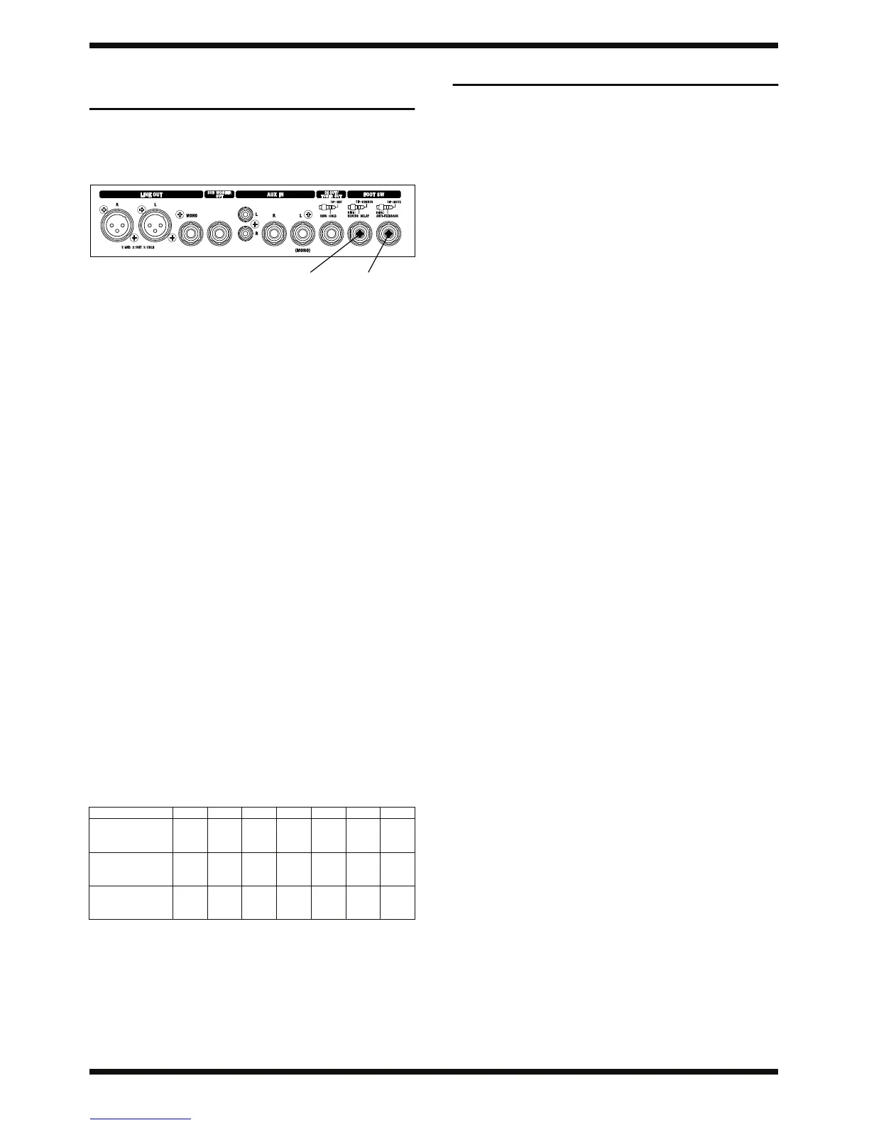
• The TIP: MUTE, RING: ANTI-FEEDBACK foot switch is indicated as
[Foot SW 1].
• The TIP: CHORUS, RING: REVERB/DELAY foot switch is indicated as
[Foot SW 2].
fig.footSW.eps
1. Foot Switch Settings and Connections
Connect two FS-5U foot switches to [Foot SW 1] using a PCS-31 foot-
switch cable.
• Set the [POLARITY] switch on the FS-5U foot switches to the setting
opposite that of the jack.
• Connect the standard plugs to the respective FS-5U foot switches.
* The PCS-31 foot-switch connection cable is a stereo to standard x 2 adapter
cable.
* On the standard plug, “white” is [TIP] and “red” is [RING].
* You can connect the white and red sides to either FS-5U unit.
2. Panel Settings
[PICKUP] switch: PIEZO
[SELECT] switch: LINE
All other switches: OFF
All volume knobs: MIN
* The unit will not enter the Test mode unless the panel settings in 2 above are
made correctly.
3. Displaying the Version Number
• With the settings in 1 and 2 above made, hold the [TIP] (white) foot
switch hold down and switch on the power.
After turning on the power, depressing the foot switch twice within 4
seconds makes the unit enter the Test mode.
* Immediately after the unit enters the Test mode, the following LEDs flash several
times (for approximately 2 seconds).
* The LEDs are used for verifying passing or failing of the inspection tests.
GUITAR channel [CHORUS] LED
MIC/LINE channel [CHORUS] LED
[ANTI-FEEDBACK] LED
[MUTE] LED
• After that, the [ANTI-FEEDBACK] and [MUTE] LEDs light up as a
display to identify the AC-90.
• Depressing the [TIP] (white) foot switch once while in this state makes
the LEDs flash to indicate the software version.
●: flashing/—: dark
4. After verifying the version, to quit the Test mode, switch off the power.
Test Mode
1. Items Required
• Headphones -- 1 set
• Boss FS-5U foot switches (sold separately) -- 2
• Roland PCS-31 foot-switch connection cable (sold separately)) -- 1
• Tester (for measuring voltage)
• Boss DI-1 (only when inspecting the signal level)
• Level meter (only when inspecting the signal level)
• Signal generator (only when inspecting the signal level)
2. Entering the Test Mode
Follow steps 1 through 3 of Verifying the Version Number.
3. Quitting the Test Mode
Switch off the power.
4. Skipping
No skipping of items in the Test mode is possible.
Version 1.00 1.01 1.02 1.03 1.04 1.05 1.06
Gt. CHANNEL
[CHORUS]
LED
● — — ● ● — ●
MIC.
[CHORUS]
LED
— ● — ● — ● ●
[ANTI-
FEEDBACK]
LED
— — ● — ● ● ●
Foot SW 2
Foot SW 1
 Loading...