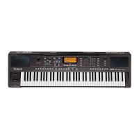
EXR-7
Apr.2004
SERVICE NOTES
Issued by RES
First edition
SPECIFICATIONS 2
DISASSEMBLY 3
LOCATION OF CONTROLS 4
EXPLODED VIEW (TOP) 6
EXPLODED VIEW (BOTTOM) 7
KEYBOARD PARTS LIST 8
PARTS LIST 10/13
HOW TO SAVE - HOW TO VERSION UP 14
HOW TO VISUALIZE THE SOFTWARE VERSION 14
HOW TO SAVE THE SOFTWARE ON A FLOPPY DISK 14
HOW TO UPDATE THE SOFTWARE 15
HOW TO CARRY OUT THE FACTORY SETUP 15
TEST MODE 16/24
BLOCK DIAGRAM 26
CIRCUIT BOARD (MAIN) 28
CIRCUIT DIAGRAM (MAIN 1/7) 30
CIRCUIT DIAGRAM (MAIN 2/7 - XP section) 32
CIRCUIT DIAGRAM (MAIN 3/7 - KEY section) 34
CIRCUIT DIAGRAM (MAIN 4/7 - MEMORY section) 36
CIRCUIT DIAGRAM (MAIN 5/7 - D-BEAM section) 38
CIRCUIT DIAGRAM (MAIN 6/7 - FDC section) 40
CIRCUIT DIAGRAM (MAIN 7/7 - USB section) 41
CIRCUIT BOARD (JACK) 42
CIRCUIT DIAGRAM (JACK) 44
CIRCUIT BOARD (RIGHT CONTROL/D-BEAM) 46
CIRCUIT DIAGRAM (RIGHT CONTROL/D-BEAM) 48
CIRCUIT BOARD (LEFT CONTROL) 50
CIRCUIT DIAGRAM (LEFT CONTROL) 52
CIRCUIT BOARD (PHONES) 54
CIRCUIT DIAGRAM (PHONES) 55
CIRCUIT BOARD (VOLUME) 54
CIRCUIT DIAGRAM (VOLUME) 55
CIRCUIT BOARD (SWITCH) 54
CIRCUIT DIAGRAM (SWITCH) 55
CIRCUIT BOARD (CONTACT BOARD) 56
CIRCUIT DIAGRAM (CONTACT BOARD) 58
SN00075 K6018551 Printed in Italy
EXR-7
interactive arranger
TABLE OF CONTENTS
Copyright © 2004 by ROLAND CORPORATION
All rights reserved. No parts of this publication may be reproduced in any form whithout the written permission of
ROLAND CORPORATION.

 Loading...