5
placed between the two ring gears. The bevel pinion can then
be engaged with the two ring gears.
10. With shims (121) in place, insert the pinion shaft assembly
into the side of the drive head housing, and bolt in place with
seven cap screws (124), and washers (123).
SETTING CLEARANCE BETWEEN
GEARS AND PINION
The backlash between the ring gears and pinion should be set
to the figures in Table 1, depending on the method being used.
The vertical adjustment for gear alignment is accomplished
by means of shims (55) which are placed between the lower
bearing rest casting (60) and the lower bearing support collar
(54).
The horizontal adjustment for backlash between the pinion and
the gears is accomplished by means of shims (121) between the
pinion shaft housing (122) and the drive head housing.
Table 2 shows the color coding for shim thickness.
To check the backlash between gears, first lock the pinion shaft
by clamping the shaft to a threaded rod which has been inserted
in one of the tapped holes in the pinion housing. If measuring
directly on the gear teeth, insert a dial indicator into the drive
head housing through the inspection port, so that the indicator
probe is in contact with the face of a tooth on the bottom ring
gear.
If using the ROTEX Backlash Checking Kit, thread the rod into
the tapped hole in the side of the minor weight hub and tighten
slightly. The rod should protrude through the inspection port at
right angles to the machined face of the inspection port. Mount
the magnetic back indicator on the inspection port face with the
indicator probe in contact with the threaded rod (see Figure 3).
NOTE: The threaded rod must not be used to move the weights
while taking backlash readings. Doing so will result in highly
erroneous readings.
Attempt to move the minor balance weight casting and read the
deflection on the dial indicator.
Take a backlash measurement on the upper ring gear by
applying the steps listed above to the major weight (see Figure
2). Move the crankshaft and read the deflection on the dial
indicator.
Once this has been done, rotate both the minor balance casting
and the major balance casting 180 degrees, and then take
another reading.
If the readings on the bottom gear are too high or the top gear
too low, shims must be added under the lower bearing rest to
raise the crankshaft assembly. If the readings on the bottom gear
are too low or the top gear too high, shims must be removed
from under the lower bearing rest. Removal or addition of shims
under the lower bearing rest requires removal of the pinion and
lifting of the crankshaft assembly.
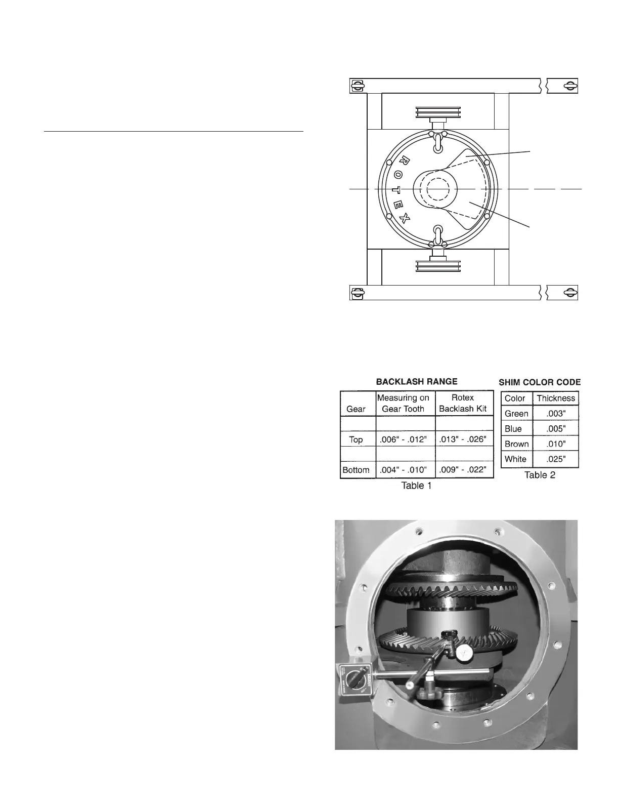
Right or Left Hand Drive - Balance weights must be positioned
one above the other 90° to center line of pinion shaft.
BALANCE WEIGHT POSITIONS FOR
DRIVE HEAD REASSEMBLY
Figure 1
Pinion Shaft
Left-Hand Drive
Pinion Shaft
Front Drive
Pinion Shaft
Rear Drive
Pinion Shaft
Right-Hand Drive
Major Weight
Minor Weight
Machine
Centerline
FIGURE 2
 Loading...