RSG2100 -______ -______ -____ -____ -____ -____ -____ -____ -____ -____ -____ -____ -____ -_____
Main Mount PS1 PS2 S1 S2 S3 S4 S5 S6 S7 S8 S9 S10
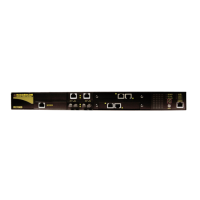
Main: Ethernet and Power Connectors
.
R =
Ethernet on rear; LED panel on front; power connector on rear
.
F =
Ethernet on front; LED panel on front; power connector on rear
.
B =
Ethernet on rear; LED panel on top; power connector on rear
.
T =
Ethernet on front; LED panel on top; power connector on rear
Mount: Mounting Options
.
RM =
19" Rack Mount Kit
.
DP =
DIN and Panel Mount Kit
.
RD = 19" Rack, DIN, and Panel Mount Kit
.
00 = No Mounting Option
PS1 and PS2: Power Supply 1 and 2
.
24 = 24VDC (9-36VDC), screw terminal block
.
48 = 48VDC (36-72VDC), screw terminal block
.
HI = 88-300VDC or 85-264VAC, screw terminal block
.
24P = 24VDC (9-36VDC), pluggable terminal block
.
48P = 48VDC (36-72VDC), pluggable terminal block
.
HIP = 88-300VDC or 85-264VAC, pluggable terminal block
.
XX = No Power Supply (PS2 Only)
S1, S2, S3, S4, S7, S8, S9 and S10:
Ethernet Modules for Slots 1, 2, 3, 4, 7, 8, 9 and 10
.
XXXX = Empty
.
TX01 = 2 x 10/100Tx RJ45
FL01 = 2 x 10FL - Multimode, 850nm, ST
.
FX01 = 2 x 100FX - Multimode, 1300nm, ST
.
FX02 = 2 x 100FX - Multimode, 1300nm, SC
.
FX11 = 2 x 100FX – Multimode, 1300nm, LC
.
FX03 = 2 x 100FX - Multimode, 1300nm, MTRJ
.
FX04 = 2 x 100FX - Singlemode, 1310nm, ST, 20km
.
FX05 = 2 x 100FX - Singlemode, 1310nm, SC, 20km
.
FX06 = 2 x 100FX - Singlemode, 1310nm, LC, 20km
.
FX07 = 2 x 100FX - Singlemode, 1310nm, SC, 50km
.
FX08 = 2 x 100FX - Singlemode, 1310nm, LC, 50km
.
FX09 = 2 x 100FX - Singlemode, 1310nm, SC, 90km
.
FX10 = 2 x 100FX - Singlemode, 1310nm, LC, 90km
S5: Gigabit Ethernet Modules for slot 5
.
XXXX = Empty
.
CG01 = 2 x 10/100/1000Tx RJ45
.
FG01 = 2 x 1000SX - Multimode, 850nm, LC, 500m
.
FG02 = 2 x 1000LX - Singlemode, 1310nm, SC connectors, 10km
.
FG03 = 2 x 1000LX - Singlemode, 1310nm, LC connectors, 10km
.
FG04 = 2 x 1000LX - Singlemode, 1310nm, SC connectors, 25km
.
FG05 = 2 x 1000LX - Singlemode, 1310nm, LC connectors, 25km
.
FG50 = 2 x 1000LX SFP - Blank (no optical transceiver)
.
FG51 = 2 x 1000SX SFP - Multimode, 850nm, LC, 500m
(3)
.
FG52 = 2 x 1000LX SFP - Singlemode, 1310nm, LC, 10km
(3)
.
FG53 = 2 x 1000LX SFP - Singlemode, 1310nm, LC, 25km
(3)
.
FG54 = 2 x 1000LX SFP - Singlemode, 1550nm, LC, 70km
(2)(3)
.
FG70 = 2 x 1000LX GBIC - Blank (no optical transceiver)
.
FG71 = 2 x 1000LX GBIC - Singlemode, 1310nm, SC, 10km
(4)
.
FG72 = 2 x 1000LX GBIC - Singlemode, 1310nm, SC, 25km
(4)
.
FG73 = 2 x 1000LX GBIC - Singlemode, 1550nm, SC, 70km
(2)(4)
S6: Gigabit Ethernet Modules for slot 6
.
XXXXX = Empty
.
1CG01 = 1 x 10/100/1000Tx RJ45
.
1FG01 = 1 x 1000SX - Multimode, 850nm, LC, 500m
.
1FG02 = 1 x 1000LX - Singlemode, 1310nm, SC connectors, 10km
.
1FG03 = 1 x 1000LX - Singlemode, 1310nm, LC connectors, 10km
.
1FG04 = 1 x 1000LX - Singlemode, 1310nm, SC connectors, 25km
.
1FG05 = 1 x 1000LX - Singlemode, 1310nm, LC connectors, 25km
.
1FG50 = 1 x 1000SX SFP - Blank (no optical transceiver)
.
1FG51 = 1 x 1000SX SFP - Multimode, 850nm, LC, 500m
(3)
.
1FG52 = 1 x 1000LX SFP - Singlemode, 1310nm, LC,10km
(3)
.
1FG53 = 1 x 1000LX SFP - Singlemode, 1310nm, LC, 25km
(3)
.
1FG54 = 1 x 1000LX SFP - Singlemode, 1550nm, LC, 70km
(2)(3)
.
1FG70 = 1 x 1000LX GBIC - Blank (no optical transceiver)
.
1FG71 = 1 x 1000LX GBIC - Singlemode, 1310nm, SC, 10km
(4)
.
1FG72 = 1 x 1000LX GBIC - Singlemode, 1310nm, SC, 25km
(4)
.
1FG73 = 1 x 1000LX GBIC - Singlemode, 1550nm, SC, 70km
(2)(4)
NOTES:
1 Distance ratings are typical but will depend on type of cabling, number of connectors and splices.
2 These transceivers have an operating temperature range of -20 °C to +85°C.
All other transceivers have an operating temperature range of -40°C to +85°C
3 SFP plugable optics that consist of a blank cage (FG50 for dual, 1FG50 for single)
plus specified fiber optic interface(s) installed
4 GBIC plugable optics that consist of a blank cage (FG70 for dual, 1FG70 for single)
plus specified fiber optic interface(s) installed
Order Codes
www.RuggedCom.com
9
RuggedSwitch
®
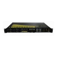
RSG2100
RuggedSwitch
®
RSG2100
19-Port Modular Managed Ethernet Switch with Gigabit Uplink Ports
Example Order Codes:
RSG2100-R-RM-24-48-TX01-TX01-XXXX-XXXX-XXXX-
XXXXX-XXXX-XXXX-XXXX-XXXX
19” Rack mounted, 24VDC power supply, 48VDC power
supply, 4 10/100 RJ45 Ethernet Ports, with Ethernet
ports on the rear
RSG2100-F-RM-48-48-TX01-TX01-FX01-FX01-XXXX-XXXXX-
XXXX-XXXX-XXXX-XXXX
19” Rack mounted, 48VDC power supply, 48VDC, 4 10/100
RJ45 Ethernet Ports, 4 100FX (Multi Mode 1300nm Fiber)
Ethernet ports, with Ethernet ports on the front
RSG2100-R-RM-HI-HI-TX01-TX01-FX01-FX01-FG02-
XXXXX-FX01-FX01-FX01-FX01
19” Rack mounted, HI power supply, HI power supply,
4 10/100 RJ45 Ethernet Ports, 12 100FX (Multi Mode 1300nm
Fiber) Ethernet ports, 2 1000LX (Gigabit) Ethernet ports,
with Ethernet ports on the front
Accessories/Options
82-01-0002 - Conformal Coating
41-11-0011 - Cable support bracket (one)
43-10-0007 - Power cable (North America three
prong connector -> beau)