Table of Figures
RuggedSwitch
®
RSG2100 5 RuggedCom
®
Table of Figures
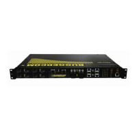
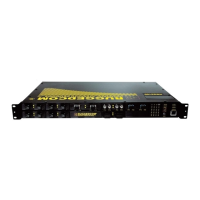
Figure 1: RSG2000 Rack mount chassis orientation options – Front and rear mount......8
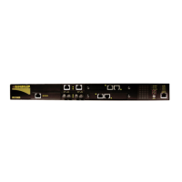
Figure 2: Ethernet, LED Status, and Power Panels.........................................................9
Figure 3: Ethernet panel LED description ........................................................................9
Figure 4: 10FL ST connector .........................................................................................10
Figure 5: 100FX MTRJ connector..................................................................................10
Figure 6: 100FX / 1000LX LC connector........................................................................10
Figure 7: 100FX / 1000LX SC connector.......................................................................10
Figure 8: 100FX / 1000LX ST connector........................................................................11
Figure 9: 1000LX GBIC Module and..............................................................................11
Figure 10: 1000LX SFP (mini-GBIC) Module.................................................................11
Figure 11: RSG2000 LED Display Panel .......................................................................12
Figure 12: RS2000 Family 19” Rack Mount Adapters....................................................14
Figure 13: Rack mount adapter mounting location ........................................................14
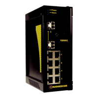
Figure 14: RSG2000 PANEL/DIN RAIL mounting diagram ...........................................15
Figure 15: RSG2000 Series Philips Screw Terminal Block.............................................16
Figure 16: RSG2000 Series Phoenix Plug Terminal Block.............................................16
Figure 17: Chassis Ground Connection..........................................................................16
Figure 18: AC Power supply wiring examples.................................................................18
Figure 19: DC Power supply wiring examples ...............................................................19
Figure 20: DC And AC power supply wiring examples ..................................................20
Figure 21: Dielectric Strength (HIPOT) Testing ..............................................................21
Figure 22: Failsafe Alarm Relay Wiring...........................................................................22
Figure 23: Console port location on display board.........................................................23
Figure 24: RSG200 Console cable ................................................................................23
Figure 25: RJ45 port pins configuration. .........................................................................24
Figure 26: SFP Orientation for top row and bottom row ports........................................26
Figure 27: Locking latch location on GBIC optical modules...........................................27
Figure 28: SFP Bail Latch location..................................................................................27
Figure 29: SFP Removal.................................................................................................27
Figure 30: RSG2000 Series Mechanical Dimensions....................................................35
Table of Tables
Table 1: LED Display – Device status LED behavior definition......................................12
Table 2: LED Display - Port LED behavior definition .....................................................13
Table 3: RSG2000 Power terminal block connection description ...................................17
Table 4: RS232 over RJ45 console cable pin-out..........................................................23
Table 5: RJ45 Ethernet pinout assignment....................................................................24
Table 6: Cabling categories and 1000BaseTx compliance defined. ..............................25
Table 7: Fast Ethernet optical specifications...................................................................30
Table 8: Gigabit Ethernet optical specifications..............................................................31
 Loading...