W
eight
Without fuel and string head
Without fuel, w/string hea
d
Fuel tank volum
e
Cutting swat
h
Engine displacemen
t
Maximum engine performance
(in accordance with ISO 8893)
Maximum rotational frequency of the the spindl
e
Engine speed (rotational frequency) a
t
recommended max. spindle rtational frequenc
y
Engine speed (rotational frequency) at idl
e
Fuel consumption (in accordance with ISO 8893
)
at max. engine performanc
e
Specific fuel consumption (in accordance with ISO 8893)
at max. engine performance
Vi
bration level idling
Front handle
Rear handl
e
Vi
bration level racing
Front handle
Rear handle
Sound pressure level (in accordance wit
h
EN ISO
11806:1997, ISO 7917:1987)
Sound power level (in accordance with ISO 10884)
4.69 Kg
5.08 K
g
425 c
m
3
433 mm
30 c
c
0.78 k
W
9000 mi
n
-1
12500 min
-1
2000-2500 min
-1
0.52 kg/h
0.47 kg/h
5.9 m/s
2
3.7 m/s
2
8.2 m/s
2
8.6 m/s
2
102 LpA (dBA)
113 LwA (dBpA)
Maintain a firm grip on both handles while trimming. Keep
bump head below waist level. Never cut with the bump
head located over 76 cm or more above the
ground
.
SPECIFIC SAFETY RULES FOR TRIMMER USE
SPECIFICATION
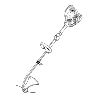
DESCRIPTIO
N
1. Starter Grip
2. Shaft
3. Throttle Trigger
4. On / Off Switch
5. Safety Button
6. Engine Housing
7. Safety Guard
8. Cutting Line
9. Bolt
10
. Flat Washer
11. Lock Washer
12. Wing nut
13. Bracket
14. Front handle
15. Choke lever
16. Run position
17. Half choke position
18. Full choke position
19. Primer bulb
20. Cutting blade
21. Rear Housing
23. Muffler Guard
24. Screws
25.
Bent End Of Muffler Guard
26.
Opening In Rear Housing
27.
Dangerous Cutting Area
28.
Best Cutting Area
29.
Direction Of Rotation
30. Bump knob
31. Spool
32
. Eyelets
33. Bump head
34. Slots
35. Spring
36. Arrow on spool
37. First line
38. Secon
d line
39. Latch
40. Cover
41. Filter
42. Slots on air filter
ASSEMB
L
Y
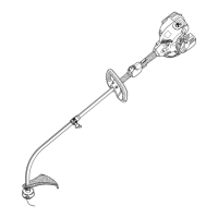
SAFETY GUARD (FIG. 2)
1.
Remove wing nut (12), flat washer (10), lock washer (11),
and
bolt (9) from the Owner's Kit.
2.
Place safety guard (7) over shaft (2) and bracket (13).
3.
Install bolt through the slots in the tabs on safety
guard
and bracket on driveshaft housing.
4.
Install flat washer, lock washer and wing nut.
4.
Tighten Securely.
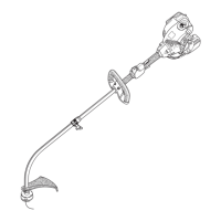
MUFFLER GUARD ASSEMBLY (FIG. 4)
1.
Remove muffler guard (23) and two screws (24) from the
owner's
kit.
47. Anchor hole
43. Tabs air filter cover
44. Idle speed screw
45. "L" Low needle
46.
"H" High needle
22. Torx Wrench
48. Fuel cap
NOTE:: Make sure the bent end of the muffler guard (25) fits
securely
into the opening of the rear housing (26).
2.
Attach the muffler guard to the rear housing (21).
3.
Using the torx wrench supplied, install the two screws
and
tighten securely.
- 3 -
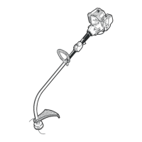
FRONT HANDLE (FIG. 3)
1. Remove the front handle (14), bolt, and wing nut from the
Owne
rʼs Kit.
2. Install the front handle onto the top side of the drive
shaft
housing and move it to a comfortable position.
3. Place the bolt through the front handle as shown, then
install
the wing nut.
4. Tighten wing nut securely.
NOTE: Do not attempt to remove or modify the spacer.
This
spacer limits the upper position of the handle grip.
 Loading...