1. Connection Po
2. Feed the positive and negative cables into corresponding lock screws and crimp them tightly
with a wire crimper. Make sure that the withdrawal force of the pressed cable is larger than
400N.
3. Plug in the pressed positive and negative cables into relevant insulated enclosure, a “click”
sound should be heard when the contact cable assembly is seated correctly.
4. Fasten the lock screws on positive and negative connectors into corresponding insulated
enclosure and make them tight.
5. Connect the positive and negative connectors into positive and negative DC input terminals
of the inveer, a “click” sound should be heard when the contact cable assembly is seated cor-
rectly.
Figure4.8
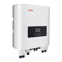
Connect to the Inveer
· Before inse the connector into DC input terminal of the inveer, please make sure that the DC switch of the inveer is OFF.
·Please use the original H4 terminal to install.
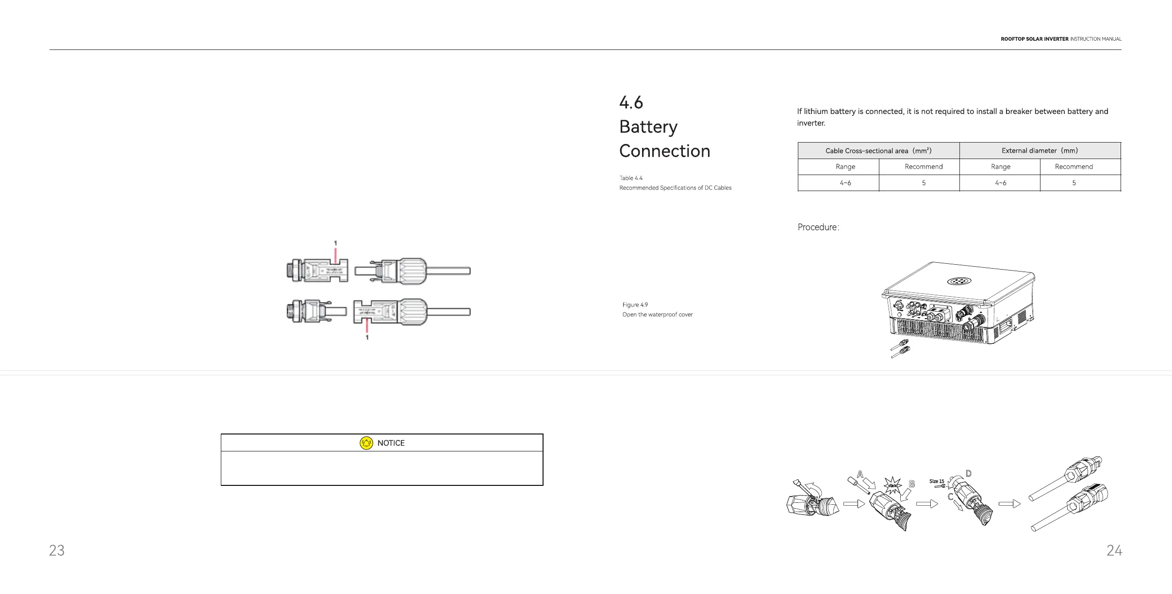
Procedure:
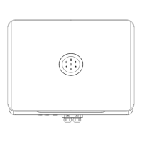
1.Open the waterproof cover, then feed the batte cable through the AC waterproof hole.
Figure 4.10
Batte Terminal
2.• Strip o the insulation skin of DC cable, the core is exposed to 15mm,
• Open the spring using a 3mm wide bladed screwdriver
• Carefully inse the stripped wire all the way in
• The wire ends have to be visible in the spring
• Close the spring. Make sure that the spring is snapped in
• Inse the cable into the sleeve
• Tighten the cable gland
 Loading...