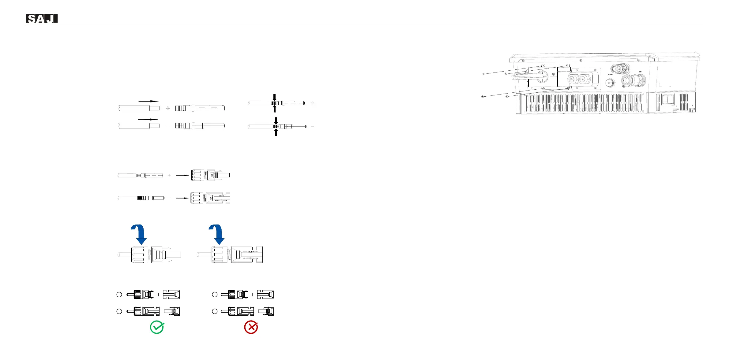
Procedure
1. Insert the positive and negative cables through the hole in the waterproof cover. (This cover has been
used in battery connection.)
2. Use a 3-mm wide-bladed screwdriver to strip the insulation layer around 8 to 10 mm length from one
end of each cable.
3. Insert the cable ends to the sleeves. Use a crimping plier to assembly the cable ends.
4. Insert the assembled cable ends into the blue positive and negative battery connectors. Gently pull the
cables backwards to ensure firm connection.
5. Tighten the lock screws on the positive and negative cable connectors.
6. Connect the positive and negative cable connectors into the positive and negative PV ports on the
inverter. After you hear a “click” sound, the cables are firmly connected.
7. Install the waterproof cover for PV and battery ports. Tighten the screws.
-- End
4.8. Earth Fault Alarm
This inverter complies with IEC 62109-2 clause 13.9 for earth fault alarm monitoring. If an earth fault alarm
occurs, the ring light on the inverter LED panel will be lit up in red and an error code <31> can be viewed on
the eSAJ Home App.
NOTE: The inverter cannot be used with functionally earthed PV arrays.
4.9. System connection
The system connection is as shown below.
⚫ For safety, the neutral (N) cables of the grid and backup-load sides must be connected together.
⚫ The PE terminal of the BACK-UP port is not connected.
⚫ The E-BAR and the N-BAR must be short-circuited.
 Loading...