S&C ELECTRIC COMPANY
s
716-501
INSTRUCTION SHEET
Page 26 of 26
August 12, 2002
S&C Series 2000 Circuit-Switchers Model 2010 — With Horizontal Interrupters and
Outdoor Transmission (69 kV through 230 kV) Vertical-Break Power-Operated Disconnect
OPERATION — Continued
padlocked open. In addition, the interrupters may now be
closed and re-tripped as desired, either electrically or
manually.
To recouple, open the Circuit-Switcher electrically or
manually. Then engage the decoupling handle on the rear
of the operator by pivoting it inward. See Figure 17 (top).
The disconnect-lade power train may now be padlocked
coupled.
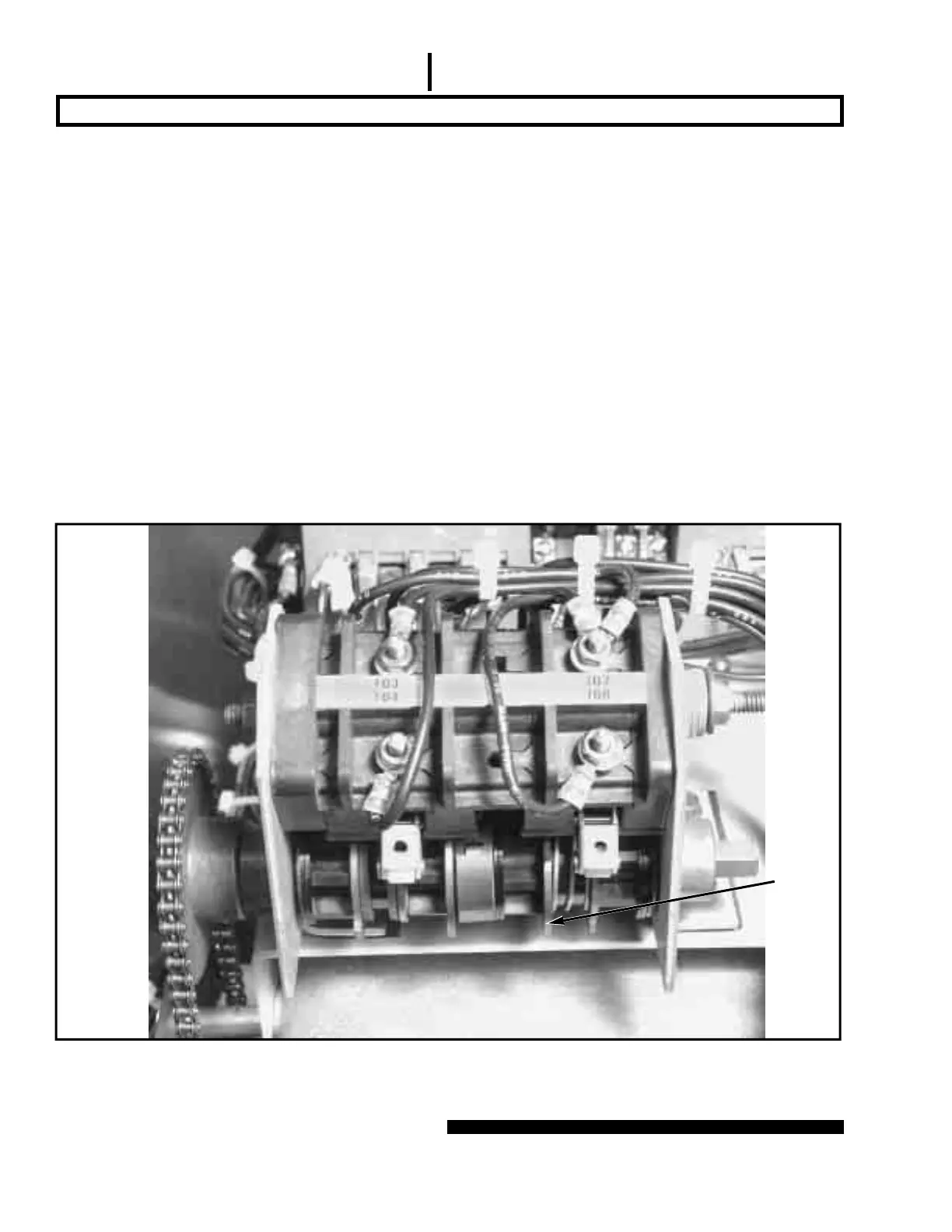
Adjusting Auxiliary-Switch Contacts
Two individually adjustable auxiliary-switch contacts are
furnished in the operator. These contacts follow the posi-
tion of the disconnect-blade power train and operator
when the power train is coupled, and the position of the
operator when the power train is decoupled.
Each auxiliary-switch contact is operated by a cam-
actuated roller. A contact is closed if its roller is disen-
gaged from a cam and, conversely, a contact is open if its
roller is engaged by a cam. The cams are individually
adjustable in 4.5-degree increments. Adjustment of the
cams is accomplished as follows:
(a) Push the cam toward its adjacent spring until the cam
is separated from the teeth of the inner gear. See
Figure 18.
(b) Rotate the cam to advance or retard engagement with
its roller.
(c) Release the cam, making sure that the teeth are in
mesh with the inner gear.
Figure 18. Adjustment of cams on auxiliary switch.
Cam
 Loading...

