14 S&C Instruction Sheet 1041-550
IntelliLINK
Using IntelliLINK
to Locate Problems
The OPERATION and TROUBLESHOOTING screens can help you check the present
status of the switch control and locate the causes of several types of problems. For more
information about events that can cause problems, see View the Fault Events Log in the
Operations Instruction Sheet 1041-540.
View the Operation Screen
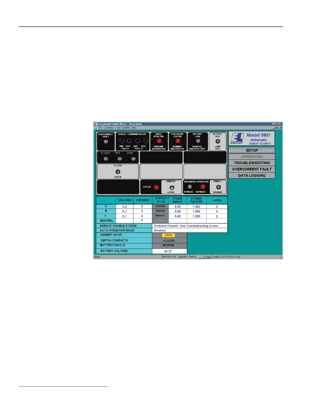
The OPERATION screen (Figure 3) shows the present status of various switch control
settings, any existing fault and error conditions, the battery, and the power line.
To display the OPERATION screen:
This is the screen that first appears when you start the IntelliLINK software. To access it
from any other screen, click the Operation button.
Figure 3. OPERATION screen (S&C 5801 shown).
The upper part of the screen reflects the status of the LEDs on the faceplate. For a full
description of these LEDs and their meanings, see the Operations Instruction Sheet 1041-
540.
This screen also includes the following fields:
AC RMS Data (Voltage, Current, Phase Ang., Rev. Current, Power Fac., kVARs)
These are the true RMS amplitude measurements for the three phases on each feeder.
Only RMS current values are logged for Switch 3, if applicable. The switch control takes
a measurement every 0.2 seconds. Then it averages 8 measurements and displays the 1.6
second averaged value.
The control measures the phase angles between the voltage and current waveforms. The
angle is displayed as a value between +90 degrees and -90 degrees. A negative value indi-
cates a leading power factor.
 Loading...
