85264190509000 © SANYO 2010
Contents
Page
IMPORTANT!
Please Read Before Starting .................................. 2
1. GENERAL .......................................................... 3
1-1. Tools Required for Installation (not supplied)
1-2. Accessories Supplied with Unit
1-3. Optional Copper Tubing Kit
1-4. Type of Copper Tube and Insulation Material
1-5. Additional Materials Required for Installation
2. INSTALLATION SITE SELECTION ................... 4
2-1. Indoor Unit
2-2. Connecting Indoor Units
2-3. Outdoor Unit
2-4 Baffle Plate for the Outdoor Unit
2-5. Outer Dimensions of Outdoor Unit
2-6. Diagram of Outdoor Unit Installation
3. INSTALLATION PROCESS .............................. 15
3-1. Embedding the Tubing and Wiring
3-2. Use of the Flaring Method
3-3. Flaring Procedure with a Flare Tool
3-4. Caution before Connecting Tubes Tightly
3-5. Tubing Connections
3-6. Insulation of Refrigerant Tubing
3-7. Taping the Tubes
3-8. Finishing the Installation
4. AIR PURGING................................................... 18
I Air Purging with a Vacuum Pump (for Test Run)
I Pump Down
5. WIRING INSTRUCTIONS ................................. 21
5-1. General Precautions on Wiring
5-2. Recommended Wire Length and Diameter
5-3. Wiring System Diagram
5-4. How to Connect Wiring to the Terminal
5-5. Wiring Instructions for the Outdoor Unit
6. TEST RUN......................................................... 25
7. CONNECTING A HOME AUTOMATION
DEVICE ............................................................. 26
8. INSTALLATION CHECK SHEET ...................... 26
INSTALLATION INSTRUCTIONS
Model Combinations
Combine indoor and outdoor units only as listed
below.
Indoor Unit Outdoor Unit
KMS0772 CM1972A
KMS0972 CM2472A
KMS1272 CM3172A
KMS1872
KMS2472
XMS0972
XMS1272
XS1872
Power Source:
60 Hz, single-phase, 230 / 208 VAC
Be sure to connect indoor and outdoor units
only in combinations that are listed in the
combination table(s) included in the outdoor
unit package.
Connecting any other model may result in
operation failure and malfunction.
– Inverter Multi Split System Air Conditioner –
COOL/DRY Model
This air conditioner uses the new refrigerant R410A.
Be sure to read the yellow instruction sheet
attached to the outdoor unit for models using the
new refrigerant R410A.
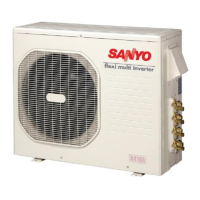
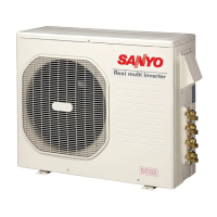
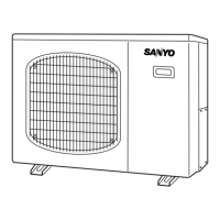
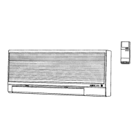
The illustrations are based on the typical appearance of
a standard model. Consequently, the shape may differ
from that of the air conditioner that you are installing.
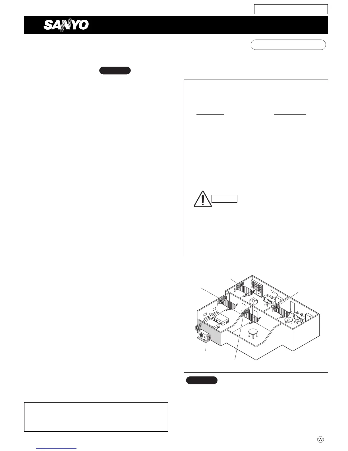
NOTE
Indoor unit A
Indoor unit B
Indoor unit C
Indoor unit D
Outdoor unit
Combination example
For Outdoor Unit
Refrigerant service valve size = 5/16"
SANYO North America Corporation In Canada
Commercial Solutions Division SANYO Canada Inc.
2055 Sanyo Ave., San Diego 201 Creditview Road, Woodbridge
CA 92154, U.S.A. Ontario, L4L 9T1, Canada
09-210 CM3172A_OU 12/11/09 5:04 PM Page a
 Loading...