EasyManua.ls Logo

Sanyo CMH3172A User Manual

Sanyo CMH3172A
134 pages
To Next Page IconTo Next Page
To Previous Page IconTo Previous Page
Page #49 background imageLoading...
Page #49 background image
Outdoor Unit : CMH1972A
Indoor Unit : KMHS0972 × 3
Power Supply : 230V Single Phase 60Hz
< Cooling Capacity >
5-2. Cooling Capacity
TC : Total Cooling Capacity (BTU/h) SHC : Sensible Heat Capacity (BTU/h)
1.
Rating conditions (#)
: Indoor Unit Entering Air Temp. 80 °F (26.7 °C) D.B. / 67 °F (19.4 °C) W.B.
: Outdoor Ambient Temp. 95 °F (35 °C) D.B.
2.
3. Above data represents the value when the operation frequency of a compressor is fixed.
Above data does not take Freeze Prevention Protection during cooling operation into account.
For this reason, the value may vary from the actual cooling characteristics.
NOTE
RATING CAPACITY: 19,100 BTU/h AIR FLOW RATE: 883 CFM
INDOOR OUTDOOR
ENT. TEMP. °F (°C) AMBIENT TEMP. °F (°C)
W.B. D.B. 65 75 85 95 105 115
(18.3) (23.9) (29.4) (35.0) (40.6) (46.1)
TC 19,180 18,500 17,770 17,210 16,350 15,440
72 (22.2) SHC 17,130 16,960 16,610 16,270 15,930 15,440
59 76 (24.4) SHC 19,180 18,500 17,770 17,210 16,350 15,440
(15.0) 80 (26.7) SHC 19,180 18,500 17,770 17,210 16,350 15,440
84 (28.9) SHC 19,180 18,500 17,770 17,210 16,350 15,440
88 (31.1) SHC 19,180 18,500 17,770 17,210 16,350 15,440
TC 20,150 19,450 18,700 18,140 17,250 16,290
72 (22.2) SHC 14,040 13,700 13,360 13,190 12,840 12,330
63 76 (24.4) SHC 16,960 16,610 16,270 16,100 15,760 15,410
(17.2) 80 (26.7) SHC 20,040 19,450 18,700 18,140 17,250 16,290
84 (28.9) SHC 20,150 19,450 18,700 18,140 17,250 16,290
88 (31.1) SHC 20,150 19,450 18,700 18,140 17,250 16,290
TC 21,140 20,420 19,640 # 19,100 18,180 17,180
72 (22.2) SHC 10,610 10,440 10,100 9,930 9,590 9,240
67 76 (24.4) SHC 13,700 13,360 13,010 12,840 12,500 12,160
(19.4) 80 (26.7) SHC 16,790 16,440 16,270 15,930 15,760 15,240
84 (28.9) SHC 19,700 19,530 19,190 19,010 18,180 17,180
88 (31.1) SHC 21,140 20,420 19,640 19,100 18,180 17,180
TC 22,130 21,400 20,600 20,080 19,130 18,100
72 (22.2) SHC 7,190 7,010 6,670 6,500 6,160 5,810
71 76 (24.4) SHC 10,100 9,930 9,590 9,410 9,240 8,900
(21.7) 80 (26.7) SHC 13,360 13,010 12,840 12,670 12,330 11,990
84 (28.9) SHC 16,270 16,100 15,760 15,590 15,240 14,900
88 (31.1) SHC 19,190 19,010 18,670 18,500 18,330 17,990
TC 23,020 22,270 21,450 20,980 20,000 18,930
75 76 (24.4) SHC 6,840 6,670 6,330 6,160 5,980 5,640
(23.9) 80 (26.7) SHC 9,930 9,760 9,410 9,240 9,070 8,730
84 (28.9) SHC 12,840 12,670 12,500 12,330 11,990 11,640
88 (31.1) SHC 15,930 15,590 15,410 15,240 14,900 14,730
47

Other manuals for Sanyo CMH3172A

Question and Answer IconNeed help?

Do you have a question about the Sanyo CMH3172A and is the answer not in the manual?

Sanyo CMH3172A Specifications

General IconGeneral
BrandSanyo
ModelCMH3172A
CategoryAir Conditioner
LanguageEnglish

Summary

Notice and Product Identification

Correction and Production Change Information

Indicates sections for corrections, service flashes, production changes, or added information.

Product Model and Capacity Summary

Provides a summary of outdoor unit models, capacities, and product codes.

Technical & Service Manual Overview

Outdoor Unit Identification and Applicable Indoor Units

Identifies outdoor units and lists compatible indoor unit types.

Safety Precautions

General and Electrical Safety Guidelines

Covers general safety, electrical shock warnings, and proper wiring practices.

Refrigerant, High Place, and Maintenance Safety

Details safety for refrigerant handling, working at heights, and maintenance procedures.

Applicable Indoor Units

Wall Mounted and Semi-Concealed Unit Compatibility

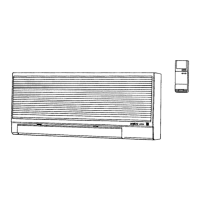
Details compatibility tables for wall-mounted and semi-concealed indoor units.

Operating Range Specifications

Cooling and Heating Temperature Limits

Specifies the operational temperature ranges for cooling and heating modes.

Unit Specifications Overview

CMH1972A 230V Specifications

Detailed specifications for the CMH1972A outdoor unit at 230V.

CMH1972A 208V Specifications

Detailed specifications for the CMH1972A outdoor unit at 208V.

CMH2472A 230V Specifications

Detailed specifications for the CMH2472A outdoor unit at 230V.

CMH2472A 208V Specifications

Detailed specifications for the CMH2472A outdoor unit at 208V.

CMH3172A 230V Specifications

Detailed specifications for the CMH3172A outdoor unit at 230V.

CMH3172A 208V Specifications

Detailed specifications for the CMH3172A outdoor unit at 208V.

Major Component Specifications

CMH1972A Outdoor Unit Components

Details on control PCB, compressor, fan motor, and heat exchanger for CMH1972A.

CMH2472A Outdoor Unit Components

Details on control PCB, compressor, fan motor, and heat exchanger for CMH2472A.

CMH3172A Outdoor Unit Components

Details on control PCB, compressor, fan motor, and heat exchanger for CMH3172A.

Other Component Specifications

Sensor Specifications and Charts

Information on sensors and corresponding resistance charts.

Dimensional Data

CMH1972A Outdoor Unit Dimensions

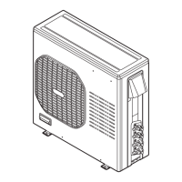
Provides detailed diagrams and measurements for the CMH1972A outdoor unit.

CMH2472A Outdoor Unit Dimensions

Provides detailed diagrams and measurements for the CMH2472A outdoor unit.

CMH3172A Outdoor Unit Dimensions

Provides detailed diagrams and measurements for the CMH3172A outdoor unit.

Refrigerant Flow and Tubing

CMH1972A Refrigerant Flow and Tubing Insulation

Illustrates refrigerant flow and specifies tubing insulation requirements.

CMH2472A Refrigerant Flow Diagram

Illustrates the refrigerant path for the CMH2472A model.

CMH3172A Refrigerant Flow Diagram

Illustrates the refrigerant path for the CMH3172A model.

Performance Data

CMH1972A Performance Charts and Notes

Cooling and heating performance charts with usage notes for CMH1972A.

CMH2472A Performance Charts

Cooling and heating performance charts for CMH2472A.

CMH3172A Performance Charts

Cooling and heating performance charts for CMH3172A.

Capacity Data

CMH1972A Cooling Capacity Tables

Tables detailing cooling capacity based on temperature conditions for CMH1972A.

CMH2472A Cooling Capacity Tables

Tables detailing cooling capacity based on temperature conditions for CMH2472A.

CMH3172A Cooling Capacity Tables

Tables detailing cooling capacity based on temperature conditions for CMH3172A.

Heating Capacity Data

CMH1972A Heating Capacity Tables

Tables detailing heating capacity based on temperature conditions for CMH1972A.

CMH2472A Heating Capacity Tables

Tables detailing heating capacity based on temperature conditions for CMH2472A.

CMH3172A Heating Capacity Tables

Tables detailing heating capacity based on temperature conditions for CMH3172A.

Electrical Data

CMH1972A Electric Wiring Diagram

Shows the electrical connections and wiring diagram for CMH1972A.

CMH2472A Electric Wiring Diagram

Shows the electrical connections and wiring diagram for CMH2472A.

CMH3172A Electric Wiring Diagram

Shows the electrical connections and wiring diagram for CMH3172A.

Unit Functions

Initial Operation and HEAT Mode

Explains initial start-up sequence and HEAT mode operations.

HEAT Mode: Defrost and Operation States

Details defrost sequences and operational states within HEAT mode.

COOL Mode and Freeze Prevention

Describes COOL mode operation, freeze prevention, and stop conditions.

SENSOR DRY Mode and Frequency Control

Explains SENSOR DRY mode and frequency control mechanisms.

Low Ambient Cooling Operation

Low Ambient Cooling Mode and Protection

Covers mode transitions and protective actions for low ambient cooling.

Protective Functions

Defrost Detection and Release

Explains the mechanisms for detecting and releasing defrost cycles.

Current Control and Frequency Adjustment

Describes how current is managed by adjusting operating frequency.

Start-up Current, Compressor Control, and HEAT Start-up

Covers low start current, compressor temp control, and HEAT start-up.

Troubleshooting Precautions

Handling High-Voltage Electronic Components

Warns about charged capacitors and safe handling of electronic boards.

Trouble Diagnosis using Error Lamps

Error Lamp Locations and Meanings

Identifies error lamp locations and their diagnostic codes.

Outdoor System Checks

Outdoor Unit Power and Defrost Test

Checks outdoor unit power, operation, and performs a defrost test.

Troubleshooting Part Diagnostics

Part-Specific Problem and Inspection Guide

Maps common problems to inspection points for various parts.

Detailed Component Inspection Points

Provides specific checks for components like fuses, compressors, and sensors.

Electric Expansion Valve Inspection

Details the procedure for testing the electric expansion valve's functionality.

Sensors, Breaker, and Refrigerant Pressure Checks

Covers checks for temperature sensors, breakers, and refrigerant pressure.

Fan Motor Troubleshooting

DC Fan Motor Symptoms and Diagnostics

Lists fan motor issues and diagnostic procedures via voltage checks.

Refrigerant R410A Servicing Precautions

R410A Refrigerant Characteristics

Explains the properties, composition, and handling of R410A refrigerant.

Servicing Checklist and Tubing Precautions

Covers pre-servicing checks, flare tool usage, and tubing precautions.

Tools for R410A Servicing

Lists specialized tools required for servicing R410A systems.

Compressor Malfunction and Replacement

Compressor Replacement Procedure

Details steps for recovering refrigerant, replacing compressor, checking seals, and evacuation.

Refrigerant Recharging Procedures

Explains refrigerant charging methods, safety, and quantity guidelines.

Refrigerant Leak Detection and Repair

Leak Detection, Repair, and Recharge Process

Outlines steps to find, fix refrigerant leaks, and recharge the system.

Additional Refrigerant and Retrofitting

Covers procedures for adding refrigerant and retrofitting existing systems.

Installation Instructions Appendix

Overview and Model Combinations

Lists installation sections and provides an overview of unit combinations.

Important Installation and Safety Guidelines

General Installation Safety and Site Selection

Covers general safety, electrical precautions, and site selection criteria.

General Installation Information

Required Tools, Accessories, and Materials

Lists necessary tools, supplied accessories, and required materials.

Installation Site Selection

Indoor and Outdoor Unit Placement Guidelines

Specifies ideal locations, areas to avoid, and clearances for unit placement.

Tubing Length and Elevation Limits

Provides specifications for maximum tubing length and elevation differences.

Connecting Indoor and Outdoor Units

CMH1972A Indoor Unit Connection Diagrams

Illustrates connection methods for indoor units with CMH1972A.

CMH2472A Indoor Unit Connection Diagrams

Illustrates connection methods for indoor units with CMH2472A.

CMH3172A Indoor Unit Connection Diagrams

Illustrates connection methods for indoor units with CMH3172A.

Outdoor Unit Installation

Outdoor Unit Placement and Baffle Installation

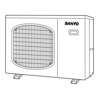
Details outdoor unit placement and the installation of wind baffle plates.

Baffle Plate Dimensions and Parts

Provides dimensions and required parts for baffle plate installation.

Installation Process Steps

Tubing, Wiring, and Flaring Procedures

Covers embedding tubing, wiring, and the flaring process.

Tube Connection Precautions and Torque

Covers cautions for tube connection and specified tightening torques.

Outdoor Unit Outer Dimensions

Dimensional Diagrams for CMH1972A/CMH2472A/CMH3172A

Provides detailed measurement diagrams for all outdoor unit models.

Outdoor Unit Installation Diagram and Clearance

Flaring Procedure and Tube Preparation

Refrigerant Tubing Installation Details

Refrigerant Tubing Insulation and Securing

Explains how to properly insulate and secure refrigerant tubing.

Air Purging Procedures

Effects of Air/Moisture and Vacuum Pump Purging

Details air purging effects and vacuum pump procedures.

Vacuum Pump Purging Steps and Precautions

Covers detailed steps for vacuum pump operation and safety.

Refrigerant Pump Down Procedure

Explains how to recover refrigerant using the pump down method.

Wiring Instructions and Precautions

General Wiring Precautions

Covers safety, grounding, and connection guidelines for wiring.

Recommended Wire Size and Length

Provides guidance on wire selection based on length and electrical codes.

Wiring System Diagrams for Unit Configurations

Shows wiring diagrams for different indoor and outdoor unit configurations.

Connecting Wires to Terminals

Explains the correct procedure for connecting wires to unit terminals.

Outdoor Unit Wiring Connections and Routing

Details connections to the outdoor unit's terminal board and cable management.

Test Run Procedures

Performing Test Run and Checking Connections

Outlines how to conduct a test run and check for tubing/wiring errors.

Installation Completion Checks

Home Automation and Final Installation Verification

Covers HA device connection and a checklist for final installation verification.

Unit Combination Tables Appendix

List of Combination Tables and Notes

Lists available combination tables and provides important operational notes.

3-Room Outdoor Unit Combinations (CMH1972A)

CMH1972A 3-Room Combinations (230V/208V)

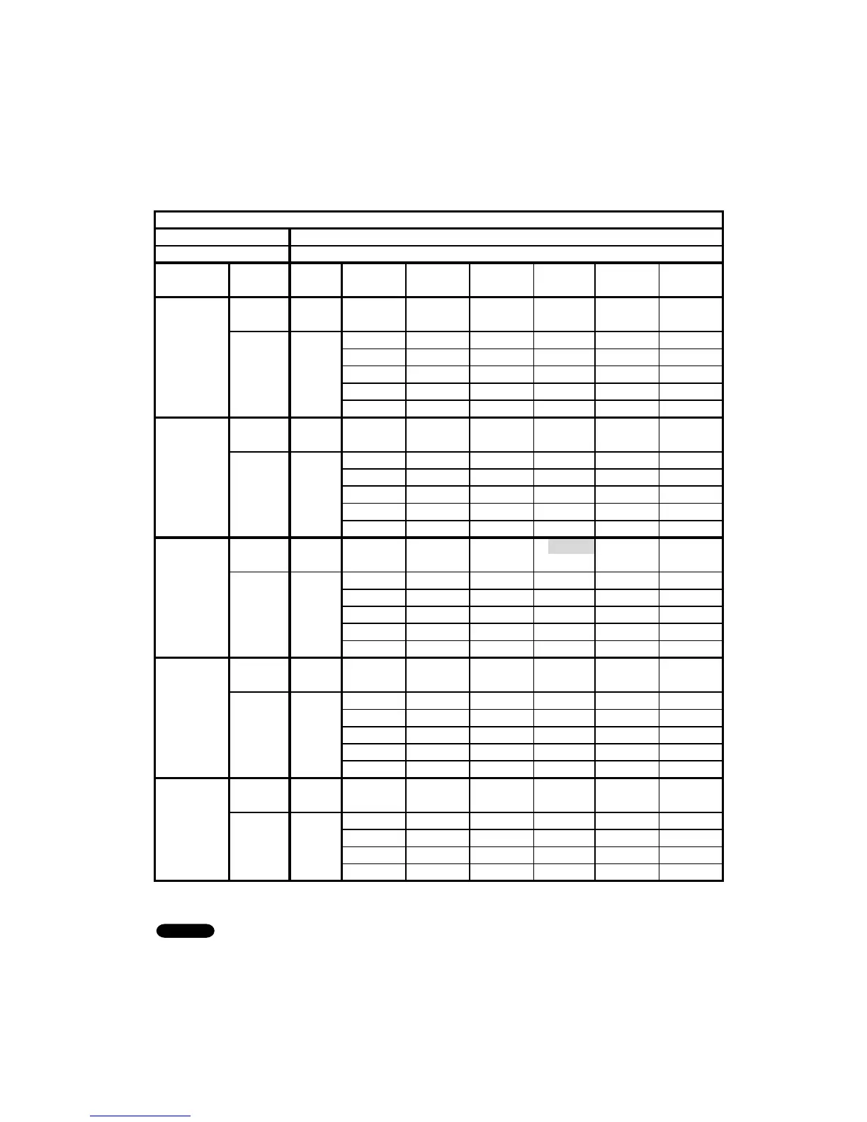
Details possible indoor unit combinations for 3-room setups with CMH1972A.

CMH1972A 3-Room Combination Table (230V)

Table listing 3-room indoor unit combinations for CMH1972A at 230V.

CMH1972A 3-Room Combination Table (208V)

Table listing 3-room indoor unit combinations for CMH1972A at 208V.

4-Room Outdoor Unit Combinations (CMH2472A)

CMH2472A 4-Room Combinations (230V)

Details possible indoor unit combinations for 4-room setups with CMH2472A.

CMH2472A 4-Room Combination Table (230V)

Table listing 4-room indoor unit combinations for CMH2472A at 230V.

CMH2472A 4-Room Combination Table (208V)

Table listing 4-room indoor unit combinations for CMH2472A at 208V.

4-Room Outdoor Unit Combinations (CMH3172A)

CMH3172A 4-Room Combinations (230V)

Details possible indoor unit combinations for 4-room setups with CMH3172A.

CMH3172A 4-Room Combination Table (230V)

Table listing 4-room indoor unit combinations for CMH3172A at 230V.

CMH3172A 4-Room Combination Table (208V)

Table listing 4-room indoor unit combinations for CMH3172A at 208V.

Related product manuals