- 3 -
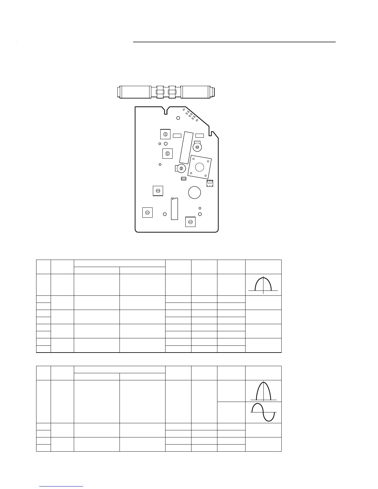
TUNER ADJUSTMENTS (Z130L)
C4
C3
C2
C1
Input
Closed the output
terminal by sweep
generator,it place
to MW ANT
Connect AM SG to
test loop
Connect AM SG to
test loop
Connect AM SG to
test loop
Connect AM SG to
test loop
Output
Connect sweep
generator to (19)
IC101(H) 0and C114(E)
Connect VTVM to
speaker terminals.
Connect VTVM to
speaker terminals.
Connect VTVM to
speaker terminals.
Connect VTVM to
speaker terminals.
Adjusting
Circuit
IF
Tuning
coverage
Tracking
Tuning
coverage
Tracking
SG
Frequency
465 KHz
515 KHz
1640 KHz
600 KHz
1400 KHz
140 KHz
290 KHz
160 KHz
250 KHz
Position of
Tuning dial
Low
Low end
High end
600 KHz
1400 KHz
Low end
High end
600 KHz
1400 KHz
VTVM
Oscilloscope
Max.
Max.
Max.
Max.
Step
1
2
3
4
5
6
7
8
9
Adjustment
T104
T102
C3
MW COIL
C4
T101
CT106
LW COIL
CT105
Connections
a. AM Adjustment Band switch : MW
Input
Connect sweep
generator to
IC101(1)pin (H) &
IC101(2)pin (E)
Connect FM SG to
JP105(H) & D102(E)
Connect FM SG to
JP105(H) & D102(E)
Output
Connect VTVM to
generator to (19)
IC101(H) and C104(E)
Connect VTVM to
speaker terminals.
Connect VTVM to
speaker terminals.
Adjusting
Circuit
IF
Tuning
coverage
Tracking
SG
Frequency
10.7 MHz
87.30 MHz
108.75 MHz
90.0 MHz
106.0 MHz
Position of
Tuning dial
Low
Low end
High end
90.0 MHz
106.0 MHz
VTVM
Oscilloscope
Max.
Max.
Step
1
2
3
4
5
Adjustment
T103
T105
L105
C1
L104
C2
Connections
b. FM Adjustment Band switch : FM FM Dummy antenna : 75 ohms unbalance
SW102
SW101
CT102
CT106
T101
T102
PUC
T103
L104
IC101
T105
T104
L105
MW COILLW COIL
Use a plastic screw driver for adjustments.
Adjust the intermediate frequency of AM and FM to the frequency of ceramic filter.
Set of unit
Supply voltage : DC 12.0V
Speaker impedance : 8 ohms
Standard output : 50 mW
Function switch : RADIO
248-130901-124
 Loading...