- 2 -
TUNER ADJUSTMENTS
Use a plastic screw driver for adjustments.
Adjust the intermediate frequency of AM and FM to the frequency of ceramic filter.
Supply voltage : DC 12.0V
Phones impedance : 32 ohms
Function switch : RADIO
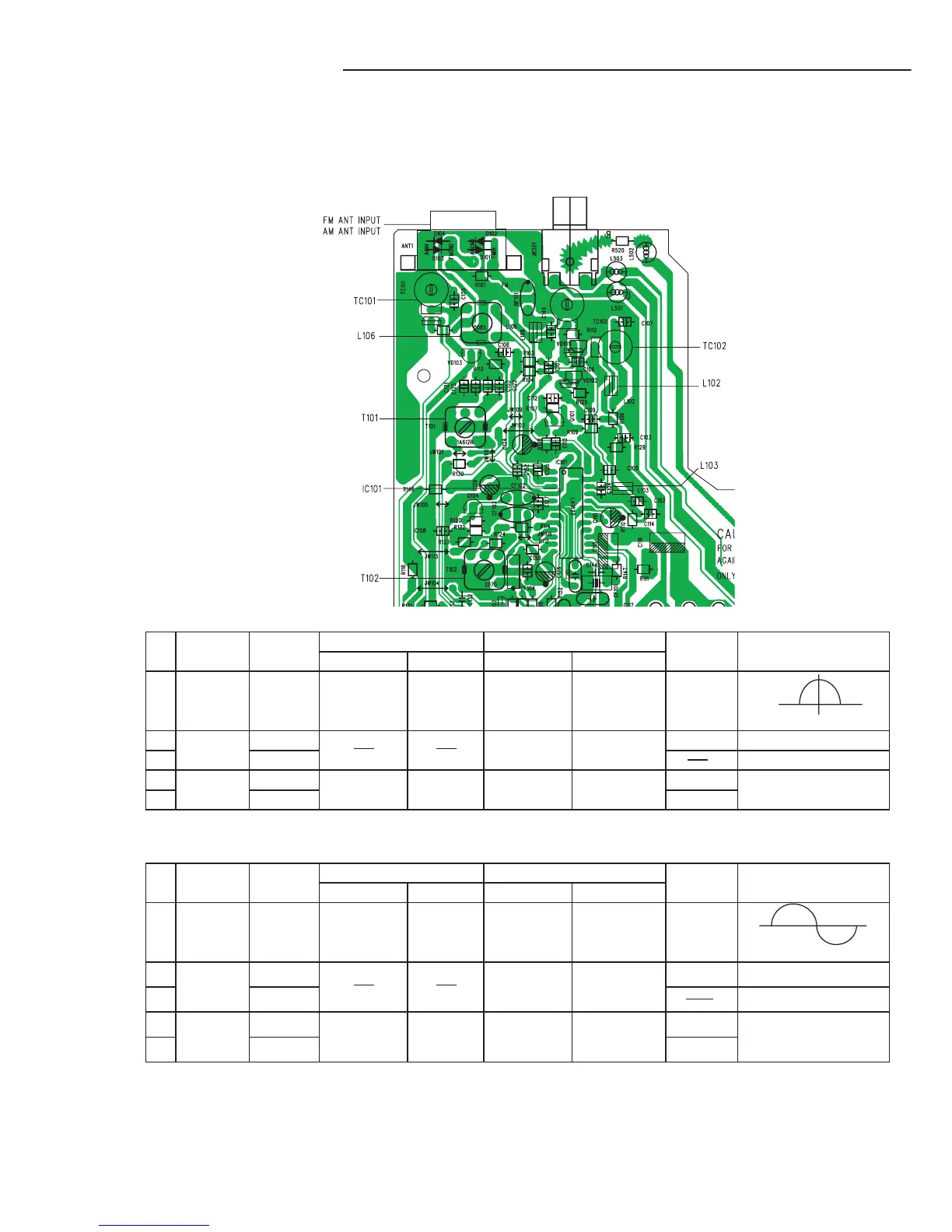
a. Parts Location
b. AM Adjustment BAND SELECT SWITCH: AM.
Ste
Adjusting Tuning Input Connection Output Connection Adjustment VTVM Oscilloscope
circuit Frequency Measurement Input
Measurement
Output Parts OR VT. VOLT.
IC101PIN19(H)
1 IF 999 kHz AM Sweep Loop ANT VTVM
IC101PIN6(E)
T102
(450 KHz) Genertor
Oscilloscope
2 Tuning 522 KHz
Digital C131(H), T101 1.50V+/- 0.05 V
3 Coverage 1611 kHz Voltmeter C131(E)
Confirm 7.8V+/-0.8 V
4 603 kHz AM Signal VTVM C146TU(L)
L106
5 Tracking 1404 kHz Generator
Loop ANT
Oscilloscope
IC101 pin6(E) TC101
Maximum
b. FM Adjustment BAND SELECT
SWITCH: FM.
FM Dummy Antenna : 75 ohm unbalance
Ste
p Adjusting Tuning Input Connection Output Connection Adjustment
VTVM Oscilloscope
circuit Frequency Measurement Input
Measurement
Output Parts
1 IF 98.0 MHz FM Sweep IC101(5)H
VTVM IC101PIN19(H)
(10.70 MHz)
Genertor IC101(6) E
Oscilloscope IC101PIN6(E)
(Non-adjustment)
2 Tuning 87.5 MHz
Digital C105(H) L103 2.0V+/- 0.2V
3
Coverage
108 MHz Voltmeter C105(E)
4 90.0 MHz FM Signal C110 (H) VTVM C146TU(L)
L102
5 Tracking 106.0 MHz
Generator
IC101(6)E
Oscilloscope
IC101 pin6(E)
TC102
Confirm6,5V+/- 0.8V
Maximum
 Loading...