CAPACITOR AND RESISTOR CODE CHART
CAPACITOR (Example)
500 C K 1500 B D ........................... ±0.5pF
T ............................ +50%
–10%
J ............................ ±5%
K ........................... ±10%
M ........................... ±20%
N ........................... ±30%
Characteristics P ...........................
+100% –0%
Value code Z ........................... +80%
–20%
Tolerance code C ........................... ±0.25pF
Material code C ........................... Ceramic
Voltage rating E ........................... Electrolytic
F ........................... Polyester
N ........................... Polypropylene
T ............................ Tantalum
K ........................... Ceramic
H ........................... MT-Composite
P ........................... NP. Electrolytic
M ........................... MT-Polypropylene
RESISTOR (Example)
6 Y K 4.7 D ........................... ±0.5%
F ........................... ±1%
G ........................... ±2%
J ............................ ±5%
Value code K ........................... ±10%
Tolerance code M ........................... ±20%
Material code F ............................ Fusible
Wattage rating N ........................... Metalized Carbon
S ........................... Oxide Metalized
Y ........................... Wire Wound
C ........................... Solid
D ........................... Carbon Film
W .......................... Wire Wound
— 53 —
— 54 —
— 56 —— 55 —
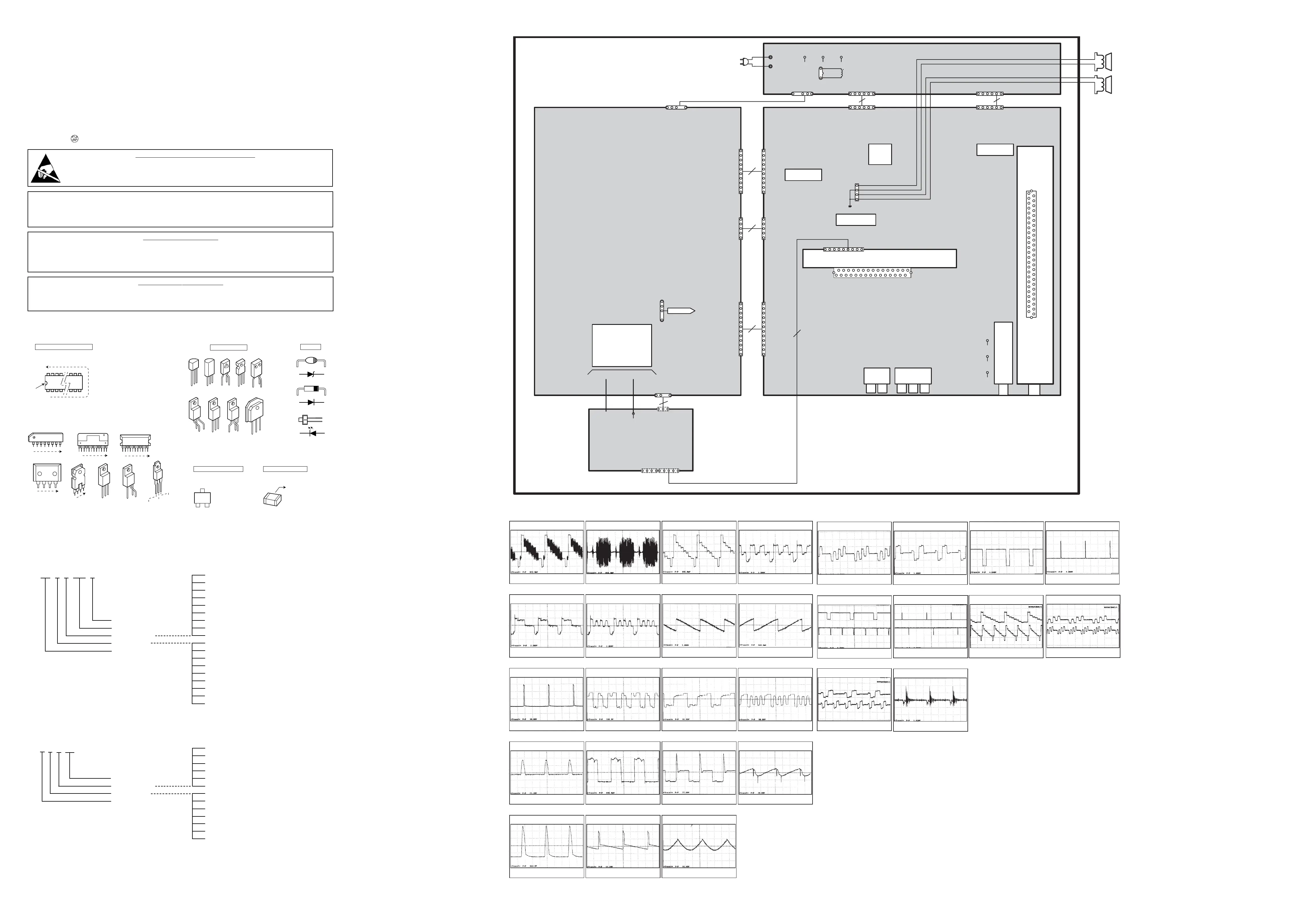
MODEL HT30746 Chassis No. 30746-00
SCHEMATIC DIAGRAMS
SERVICE NOTES:
1. When replacing parts on circuit boards, clamp the lead wires to terminals before soldering.
2. When replacing high wattage resistors on circuit board, keep the resistor body 10 mm (3/8) from circuit board.
3. Keep wires away from high voltage and high temperature components.
PRODUCT SAFET
Y NOTICE
THE COMPONENTS DESIGNATED BY A STAR (#) ON THIS SCHEMATIC DIAGRAM DESIGNATE COMPONENTS
WHOSE VALUES ARE OF SPECIAL SIGNIFICANCE TO PRODUCT SAFETY. SHOULD ANY COMPONENT
DESIGNATED BY A STAR NEED TO BE REPLACED, USE ONLY THE PART DESIGNATED IN THE PARTS LIST. DO NOT
DEVIATE FROM THE RESISTANCE, WATTAGE AND VOLTAGE RATINGS SHOWN.
X-RADIATION
WARNING NO
TE
THIS TV CONTAINS CRITICAL PARTS TO PROTECT AGAINST X-RADIATION. NOMINAL 2ND ANODE VOLTAGE IS
30.6KV AT ZERO BEAM CURRENT AT 120 VOLTS AC LINE, AND MUST NOT EXCEED 32.3KV UNDER ANY
OPERATING CONDITION. SEE HIGH VOLTAGE CHECK ON PAGE 12.
1
1
1
1
TOP VIEW
SIDE VIEW
COUNT TERMINALS IN
ARROW DIRECTION
MARK
E
C
B
AK
A
K
AK
A
K
A
K
A
K
INFRARED EMITTING
A....ANODE
K....CATHODE
INTEGRATED CIRCUITS
TRANSISTORS
1
DIODES
PHOTO COUPLERS
B ... BASE
C ... COLLECTOR
E ... EMITTER
E
C
B
E
C
B
EC
B
EC
B
E
C
B
E
C
B
E
C
B
E
C
B
3
2
1
3
2
1
GND
(2)
IN
(1)
OUT
(3)
1 1
TOP VIEW
1
CHIP TRANSISTORS
B
C
E
TOP VIEW
B ... BASE
C ... COLLECTOR
E ... EMITTER
CHIP RESISTORS
TOP VIEW
123
12 x 10 = 12K ohm
3
NOTES ON SCHEMATIC DIAGRAMS
1. All resistance values in ohms K=1,000 M=1,000,000.
2. Unless otherwise noted on schematic, all capacitor values less than 1 are expressed in µF (Micro Farad),
and the values more than 1 are in pF.
3. Unless otherwise noted on schematic, voltage reading taken with VOM from point indicated to chassis
ground. Voltage reading taken using color-bar signal VHF channel 5, all controls at normal. Line voltage at 120
volts. Some voltages may vary with signal strength.
4. Waveforms were taken with color-bar signal and controls set for normal picture. Waveforms marked with
an 8 may vary with signal strength.
5. The Symbol indicates a fusible resistor, which protects the circuit from possible short circuits.
DM
RF-TU
Regulators
CPU
Audio_Control
FBT
FOCUS SCREEN
ASSY,PWB,CRT H3EPM
ASSY,PWB,P/D-H3EPM
ASSY,PWB,MAIN-H3EMM
ASSY,PWB,FRONT-H3EPM
(247mm X 330mm)
(197mm X 330mm)
ASSY,PWB, VIDEO-H3EPM
(197mm X 123mm)
+
–
+
–
SP-L
SP-R
(5W,5X9)
Degaussing
Coil
ASSY,PWB,DIGITAL-H3EPM
K6MA
K6PDB
1
12
K6PDD
1
5
K6PDA
1
10
K9FRA
1
6
K9FRB
K6A
1
10
K4D
1
5
K5B
1
12
K4C
1
2
3
KX
1
2
3
4
X
K7U1
K6B
1
2
3
4
4
1
W601
X
A1
X
A2
K1901
K1902
1
6
DY_Coil
SP901
SP902
K1903
1
4
K1904
1
2
L901
KCRT
KSPG2
KSPG1
X
K6GND
X
KFRONT
X
KFRONT2
5
10
15
KG
1
2
20
30
25
5
10
15
1
2
20
30
25
35
40
50
45
K25A
1
9
K7D
1
5
K7E
1
4
K7C
K6FM
1
6
1
6
Regulators
Board Connection
Y
(3)
Com
osite Video
(1)
C
(2)
R
(4)
G
(5)
B
(6)
R
CRT
(10)
G (CRT)
(11)
B (CRT)
(12)
Heater
(13)
H-Drive (Base)
(14)
H-Drive
Collector
(15)
H-OUT
Base
(16)
H-OUT
Collector
(17)
V-OUT
(18)
PCC
(19)
V-Drive
+
Out
(7)
V-Drive Out
(8)
V PUMP
(9)
B-Y
(20)
R-Y
(21)
WH OUT
(22)
WV OUT
(23)
2Y (Lower)
(26)
2(B-Y) (Lower)
(27)
2
R-Y
Lower
(28)
VM
Velocit
Modulation
(29)
2H (Lower)
(24)
2V (Lower)
(25)
SCHEMATIC
WAVEFORMS
BOARD CONNECTIONS
AND LOCATIONS
ELECTR
OSTATICALLY SENSATIVE DEVICES
Many solid-state devices (especially Integrated Circuits) are Electrostatically Sensitive, and, there-
fore, require special handling techniques as described under “Servicing Electrostatically Sensitive
Devices,” on page two in this service literature.
PIN LAYOUTS
HT30746 Schematic 2006 2/13/06 1:31 PM Page 1
 Loading...