EasyManuals Logo
Home>Scheppach>Log Splitter>HL760LS

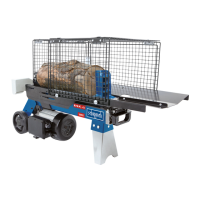
Scheppach HL760LS Translation Of The Original Instruction Manual

Scheppach HL760LS
To Next Page IconTo Next Page
To Previous Page IconTo Previous Page
Page #24 background imageLoading...
Page #24 background image
www.scheppach.com
24
|
GB
4. 


9.4 Installing the tray table (K + M) (enclosed ac-
cessories bag c + d + e) (g. 8 + 9 + 10)
1. 
     
    󰀩     

tive guard are level in relation to each other.
2. 
3. Fasten the other end of the strut to the protective
guard using the Phillips head screw and nut, align

4. 
the screw and the foot bracket, tighten the screw

5. 
6. Align both tables in relation to each other and use
󰀩
9.5 Installing the guard (E - J)
(enclosed accessories bag f) (g. 11 + 12)
1. 
Phillips head screws, clamping brackets and nuts
󰀩
2. 
this. These are on the side of the table and the pro
tective guard. Fasten the guard with seven Phillips
head screws, clamping brackets and nuts. Fit the
       
󰀩
3. 
them with eight Phillips head screws, clamping
brackets and nuts.
4. 
lips head screws, clamping brackets and nuts.
m IMPORTANT!


10. Initial operation
       






the oil level and



port damage.
In case of complaints the dealer must be informed

cepted.



iar with the device prior to using it.
       
as for wearing and spare parts. Spare parts
     


m ATTENTION
The device and packaging materials are not toys!
Children must not be allowed to play with plas-
tic bags, lm and small parts! There is a risk of
swallowing and su󰀨ocation!
9. Attachment / Before starting the
equipment
At least two people are required to install the de-
vice.
9.1 Installing the base frame (g. 3 + 4)
       


nuts provided.
1. 
2. Connect all single parts of the base frame with
the machine.
3.          

aging under the riving knife side.
4. 
frame.
9.2 Installing the handle (4) (enclosed accesso-
ries bag a) (g. 5)
       
screws.
9.3 Installing the protective guard (L) (enclosed
accessories bag b) (g. 6 + 7)
1. 

󰀩
2. 
cated on the wheel bracket.
3. Fasten the other end of the strut to the protective


Table of Contents

Other manuals for Scheppach HL760LS

Questions and Answers:

Question and Answer IconNeed help?

Do you have a question about the Scheppach HL760LS and is the answer not in the manual?

Scheppach HL760LS Specifications

General IconGeneral
Product typeElectric log splitter
Product colorBlue, Grey
Housing material-
Maximum pressure7 t
Transport wheelsYes
Maximum log length520 mm
Maximum log diameter250 mm
AC input voltage220 - 240 V
AC input frequency50 Hz
Weight and Dimensions IconWeight and Dimensions
Depth950 mm
Width330 mm
Height510 mm
Weight63000 g

Related product manuals