3.
DISASSEMBLY
6
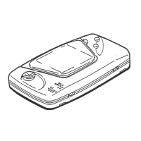
3-1. Dismantling procedure
Removal of bottom screws and top case
I) Turn
the
power button off.
2)
Turn the unit over. (See
Fig.
I)
3) Remove four screws (202).
4) Remove top case
(I
).
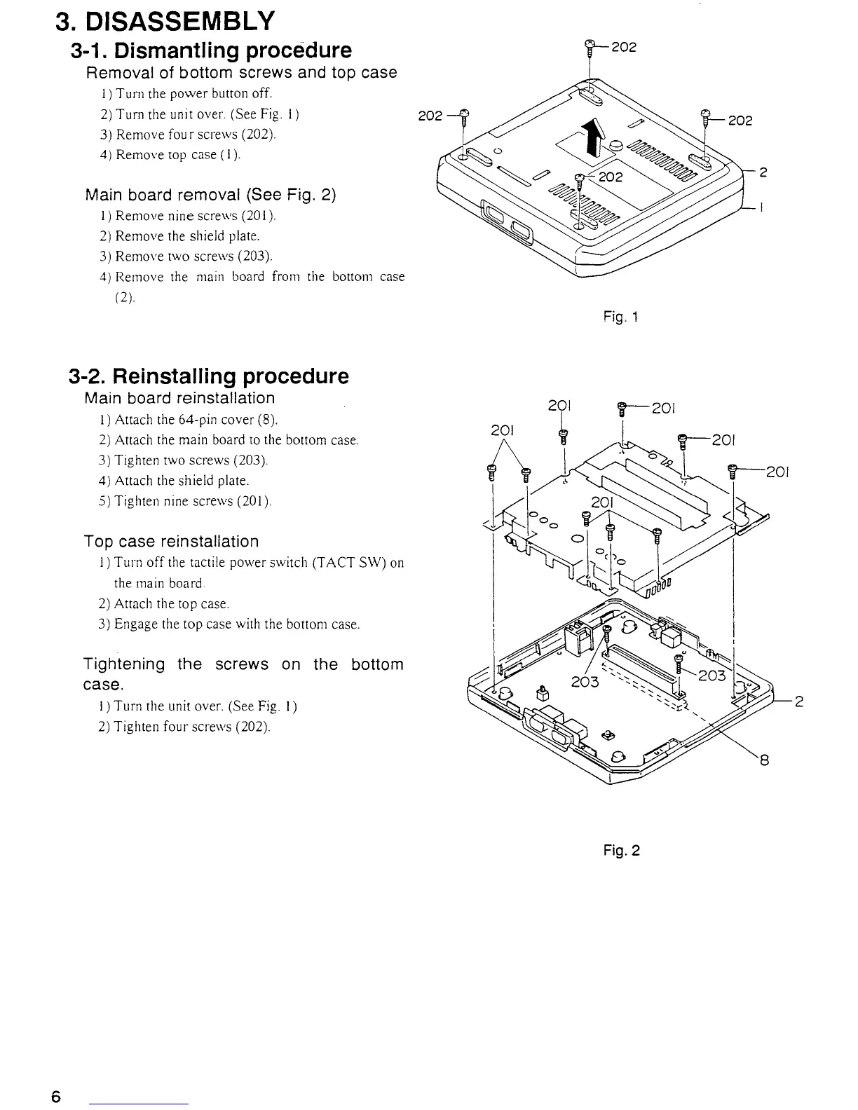
Main board removal (See Fig. 2)
I) Remove nine screws (20 I).
2)
Remove the shield plate.
3)
Remove two screws (203).
4)
Remove the
main
board from the bottom case
(2).
3-2. Reinstalling procedure
Main board reinstallation
I) Attach the 64-pin cover (8).
2)
Attach the main board
to
the bottom case.
3) Tighten
two
screws (203).
4) Attach the shield plate.
.5)
Tighten nine screws (201).
Top case reinstallation
1)
Turn off the tactile power switch (TACT SW)
on
the main board.
2)
Attach the top case.
3)
Engage the top case with the bottom case.
Tightening the screws on the bottom
case.
I) Turn the unit over. (See Fig. I)
2)
Tighten four screws (202).
201
1\
J
?-202
Fig. 1
f-"201
Fig.
2
2
2

 Loading...