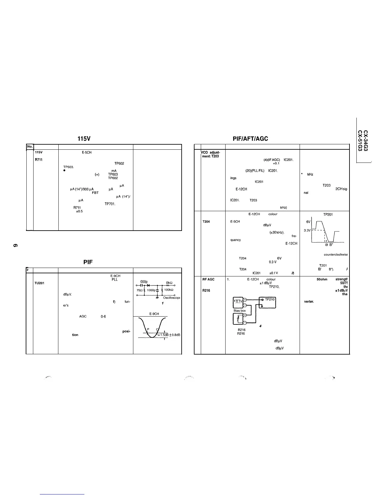
115V
ADJUSTMENT
Adjusting point
Adjusting procedure/conditions
Waveform and others
115v
1. Receive the E-5CH (monoscope pattern) signal.
adjustment:
2. Using the remote controller, call the P-NORM
R71l
mode.
3. Connect a beam ammeter between
TP602
and
TP603.
0
Ammeter’s full-scale
: 3 mA range
l Ammeter’s positive
(+)
lead :
TP603
l
Ammeter’s negative (-) lead : TP602
4. Take the beam ammeter reading to make sure
that the beam current is between 600 pA and
800
uA
(14”)/900 pA and 1100 pA (21”).
l If not, readjust the
FBT
screen control to ob-
tain the beam current of 600-800 uA (14”)/
900-1100 pA (21”).
5. Connect a digital voltmeter to TP701.
6. Adjust
R711
so that the digital voltmeter should
read 115
kO.5
V.
PIF CHECKING
Jo. Adjusting point
Adjusting procedure/conditions
Waveform and others
1 Tuner IF
1. Get the tuner ready to receive the
E-9CH
signal.
(preset):
but with no signal input. Adjust the PLL data.
IF-OUT
TU201
2. Connect the sweep generator’s output cable to
1
ooop
1
Okf;!
the tuner antenna. (RF sweep)
3. Adjust the sweep generator’s output level to 80
dBj.rV.
4. Connect the response lead (use a low-impedance
probe with wave detector; see Fig.
7)
to the
tun-
er’s
IF output terminal.
(This terminal must have the probe alone con-
nected.)
5. Set the RF
AGC
voltage to
O-6
V with no contact
with the waveform.
7s$gfjffjfOPf
Fig.
7
E-9CH
6. Adjust the tuner IF coil to obtain the waveform as
shown in
Fig. 2.
Note: Be sure to keep the tuner cover in posi-
u
P
tion during this adjustment.
-
1.5dB
+
0.8dB
Fig. 2
6-1
PIF/AFT/AGC ADJUSTMENT
lo. Adjusting point
Adjusting procedure/conditions
Waveform and others
1
VCO
adjust-
1. Disconnect the antenna from the tuner antenna
l
Warm up the unit for longer than
ment:
T203
terminal.
10 minutes in advance.
2. Apply DC voltage to pin
(4)(IF
AGC)
of
IC201.
l
DC voltage: 6.0 V (allowable +O.l V)
3. Using a digital voltmeter, measure the DC volt-
age at pin
(2O)(PLL
FIL)
of
IC201.
l The digital voltmeter must be able to take read-
*
10 kHz at about 0.007 V.
ings
down to the third decimal place.
4. Relieve pin (4) of
lC201
of the DC voltage.
5. Reconnect the antenna in position and receive
l Position the
T203
core in the
the E-12CH signal. (With the AFT off, adjust the
range in which the E-l
2CH
sig-
receiving frequency to 224.25 MHz.)
nal
can be received.
6. Connect the DC digital voltmeter to pin (20) of
IC201.
Adjust
T203
so that the voltmeter should
read the same voltage as in Step 3.
Allowable error : 0.015 V (20
kHz)
2 AFT
adjustment:
T204
3 RFAGC
cut-in
adjustment:
R216
1. Receive the
E-12CH
(PAL
colour
bar) signal. If
this signal is not available, any signal above the
E-5CH band is acceptable.
l
Field strength : 55-80 dBpV
DC voltage at
TP201
6V
Make sure the frequency is almost the same as
that of the received channel
(i30
kHz).
3.3v
-
-
-
,
2. Using the channel setting control, make a
fre-
I
quency of 224.25 MHz appear on the screen (the
I
AFT turns off). If any other channel than E-12CH
bL
DOWN A B’
;
B”
C UP
is received, make its frequency on the screen.
(The AFT turns off when the on-screen display
Fig. 3
turns yellow.)
l Turn the core
counterclockwise
3. Turn
T204
clockwise to have a
6V
point, and for the UP direction, and clock
counterclockwise to have a 0.2-V point. Position
wise for the DOWN direction.
the coil at the center of these two points.
Adjust the
T201
core to point E
4. Adjust
T204
so that the DC voltage at pin (1) (AFT
(between
B’
and
B”).
(Points
F
OUT terminal) of
IC201
be 3.3
kO.1
V (See
Fig.
3)
and C are rejectable.)
1.
Receive the
E-12CH
(PAL
colour
bar) signal.
Note: If a 500hm field
strength
l
Field strength : 57
k.1
dBpV (75 ohms open)
meter is used without a
50/X
2. Connect the oscilloscope to TP210, as shown in
impedance converter, set
thf
Fig. 4.
field strength to 55
*l
dBpV
Oscilloscope
TV Set
Pay attention to a loss
tha
would be caused with the con
m-l-v +
TP210
. . . . . .
SF
verter.
Bias box
+
Fig.
4
l
Bias box: About 6.5 V
3. Turn R216 to have the highest voltage.
4. Turn R216 slowly in the opposite direction until the
voltage goes down 0.1 V below the highest level.
5. Adjust thesignal level to 63-67 dBpV and make
sure there is no noise.
6. Now adjust the signal level to 90-95
dBuV
and make
sure there is no chrominance modulation beat.
6-2
 Loading...