-
3
Preparation
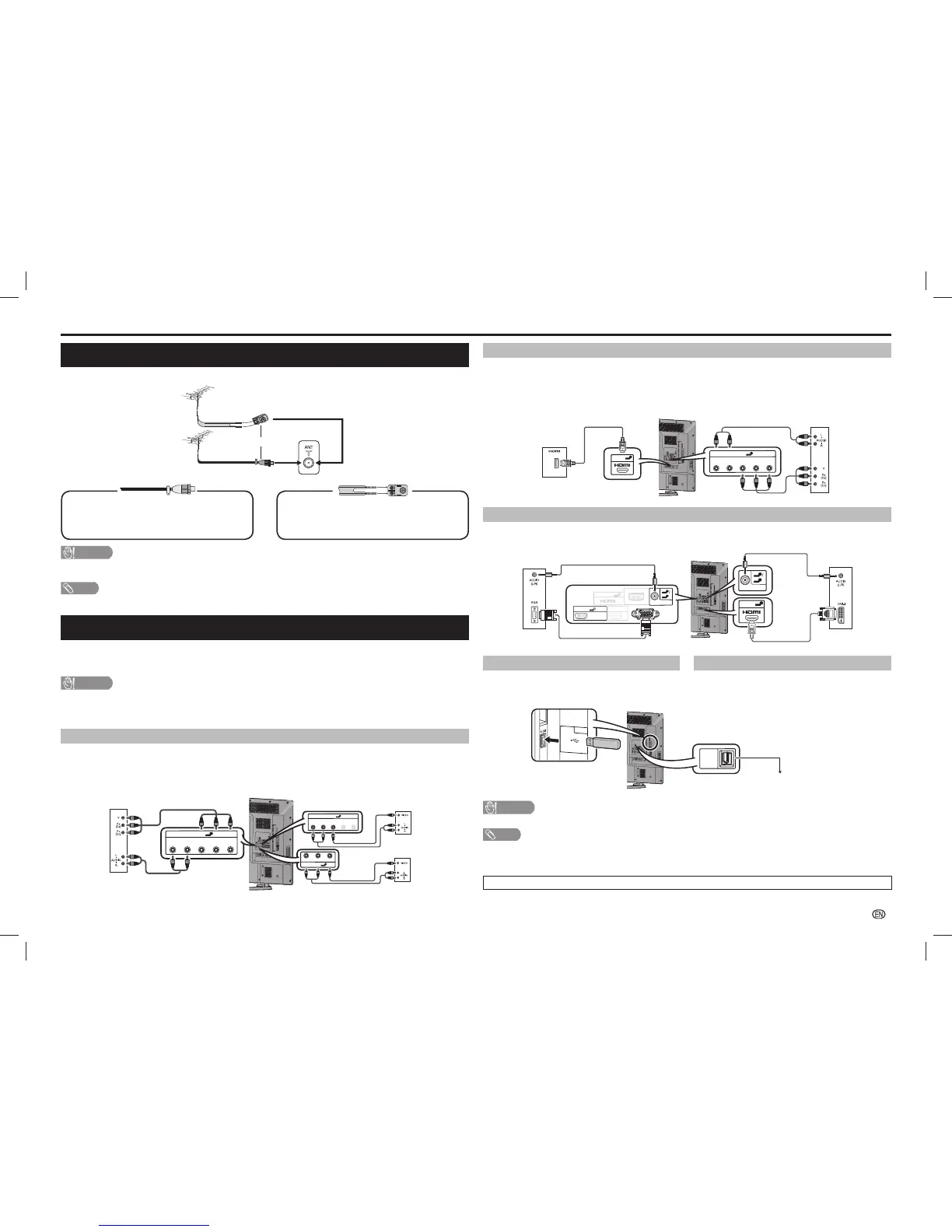
Connecting a DVD player/Digital TV STB (Set Top Box)
You can use the INPUT 1 (HDMI/ARC)/INPUT 2 (HDMI/MHL)/INPUT 3 (HDMI)/INPUT 4 (HDMI)/INPUT 5 (HDMI)
or INPUT 6 terminals when connecting to a DVD player/Digital TV STB (Set Top Box) and other audiovisual
equipment.
When using HDMI-certifi ed cable (commercially
available)
When using component cable (commercially
available)
INP
U
T
6
VI
DE
O/Y
P
B
(
C
B
)
P
R
(
C
R
)
COMPO
N
EN
T/AV I
N
P
U
T
R
S
-232
C
I
O
IOI
O
UT
P
UT
D
C
5V
1
.
5A
H
D
MI
4
H
DM
I 5
U
SB
2
D
C
5
V
0
.
5
A
5
8
AU
D
IO IN
DIG
I
T
AL
AUDIO
OUTP
U
T
ANAL
O
G
UE
RGB (
PC)
A
R
C
P
C
HDMI
1
IN
PU
T 7
A
U
D
IO
O
UT
R
- AUDIO
-
L
R - A
U
DI
O -
L
R -
A
U
D
I
O -
L
VID
EO
USB
1
DC5
V
1
.5A
3
C.
I
.
2
H
DMI 2
OU
T
P
U
T
HDM
I
3
A
UDI
O
(
L
/R
)
M
H
L
(
D
C
5V
90
0mA
)
5
HDMI 5
6
INPUT 6
R - AUDIO - L
VIDEO/Y
P
B
(C
B
)
P
R
(C
R
)
COMPONENT/AV INPUT
DVD player/
Digital TV STB
(Set Top Box)
DVD player/
Digital TV STB
(Set Top Box)
Connecting a PC
You can use the INPUT 8 PC terminals when
connecting to a PC of ANALOGUE RGB terminal.
You can use the INPUT 5 (HDMI) terminal when
connecting to a PC of DIGITAL DVI terminal.
INPUT 6
V
IDE
O
/Y
P
B
(
C
B
)
P
R
(C
R
)
C
OM
P
O
N
E
N
T/
A
V I
NP
UT
RS-2
3
2C
IOIO
I
OUTP
U
T
DC
5
V
1
.5
A
HD
M
I
4
H
DM
I 5
U
SB
2
D
C5
V
0
.
5A
5
8
AU
D
IO
IN
DI
GI
T
A
L
AU
DIO
O
UTP
UT
ANA
LOG
U
E
RGB (
PC
)
ARC
PC
HD
MI
1
IN
PU
T
7
AUDIO OUT
R
- A
U
DIO
-
L
R -
A
U
DI
O
-
L
R
-
AUDIO
- L
VID
EO
US
B
1
DC5
V
1.5A
3
C.I.
2
H
D
MI 2
O
UTPU
T
HDMI 3
AUDIO
(
L
/R)
M
H
L
(
DC5V
90
0
m
A
)
5
8
AUDIO IN
5
HDMI 5
5
8
AUDIO IN
ARC
1
HDMI 1
PC
ANALOGUE
RGB (PC)
RS-232C IOIOI
ANALOGUE
PC
ANALOGUE RGB DIGITAL DVI
PC
Connecting a USB device
Connect a USB device to the TV.
Using Digital Audio Output
It is possible to output audio through the DIGITAL
AUDIO OUTPUT terminal. PCM audio outputs from
the terminal.
INPUT 6
VIDEO/Y
P
B
(C
B
)
P
R
(
C
R
)
COMPO
N
EN
T/A
V
INP
UT
RS-232C
IOIOI
OUTP
UT
DC
5V
1.5A
HD
M
I
4
H
DMI 5
U
SB 2
DC
5
V
0.5A
5
8
AUDIO IN
D
IGIT
AL
A
U
DIO
OUTP
UT
ANALOG
UE
RGB (PC)
ARC
PC
HDMI
1
INPU
T 7
AUDIO OUT
R
-
AUDIO
-
L
R - AUDI
O -
L
R - AUDI
O - L
VIDEO
USB 1
D
C5V
1.5A
3
C.I.
2
H
DMI
2
OUTPUT
HD
MI 3
AU
D
IO
(L/
R)
MHL
(D
C5V
900mA
)
DIGITAL
AUDIO
OUTPUT
USB 1
DC5V 1.5A
To optical digital input of
external audio devices
Optical fi bre cable
(commercially available)
CAUTION
• Do not disconnect a USB device from the TV while transferring fi les, when a screen is in “USB” mode.
NOTE
• The DIGITAL AUDIO OUTPUT terminal usually outputs the same audio from the speakers. (The audio of the content you are
viewing is output from the terminal.)
• The DIGITAL AUDIO OUTPUT terminal does not output some signals, depending on devices and software.
• The illustrations used throughout this manual are based on LC-60LE660X.
Antenna connection
Connect antenna cable to the antenna terminal
or
If your outdoor antenna uses a 75-ohm coaxial cable
with a standard DIN45325 plug (IEC 169-2), plug it into
the antenna jack at the rear of the set.
If your outdoor antenna uses a 300-ohm twin-lead fl at
feeder, connect a 300-ohm to 75-ohm impedance
converter and plug it into the antenna jack at the rear of
the set.
CAUTION
• TO PREVENT RISK OF ELECTRIC SHOCK, DO NOT TOUCH UN-INSULATED PARTS OF ANY CABLES WITH THE
AC CORD CONNECTED.
NOTE
• Place the TV close to the AC outlet, and keep the power plug within reach.
Connecting external devices
You can connect many types of external equipment to your TV, like a VCR, game console, camcorder, DVD
player, Digital TV STB (Set Top Box) and PC. To view external source images, select the input source from
INPUT on the remote control unit or INPUT on the TV.
CAUTION
• To protect all equipment, always turn off the TV before connecting to a VCR, game console, camcorder, DVD player, Digital
TV STB (Set Top Box), PC or other external equipment.
• Refer to the relevant operation manual (VCR, DVD player, etc.) carefully before making connections.
Connecting a VCR, game console or camcorder
A VCR, game console, camcorder and some other audiovisual equipment can be conveniently connected
using the INPUT 6 or INPUT 7 terminals.
When using component cable (commercially
available)
When using composite cable (commercially
available)
VCR/Game
console/
Camcorder
VCR/Game
console/
Camcorder
8
INPUT 6
VIDEO/Y
P
B
(C
B
)
P
R
(C
R
)
COMPON
ENT/AV INP
UT
RS-232C IOIOI
OUTP
UT
DC5
V 1.5A
HDM
I 4
H
DMI 5
U
SB
2
DC5
V 0
.
5A
5
8
AUDIO IN
DIGITAL
AUDIO
OUTPUT
ANALOGUE
RGB (PC)
ARC
PC
HDM
I 1
INPU
T 7
AUDIO OUT
R
- AUDIO
-
L
R - A
U
DI
O
- L
R - AUD
I
O
- L
VIDEO
US
B
1
DC5V 1.5A
3
C.I.
2
HDMI 2
OUTPUT
HDMI 3
AUDIO
(L/R)
MHL
(DC5V 9
00mA)
7
INPUT 7
R - AUDIO - L
VIDEO
6
INPUT 6
6
INPUT 6
R - AUDIO
- L
VIDEO/Y
P
B
(C
B
)
P
R
(C
R
)
COMPONENT/AV INPUT
COMPONENT/AV INPUT
R - AUDIO - L
VIDEO/Y P
B
(C
B
)
P
R
(C
R
)
or
LC-406070LE660X_EN_GXX.indd 3LC-406070LE660X_EN_GXX.indd 3 9/2/2014 9:23:32 AM9/2/2014 9:23:32 AM
 Loading...