LC-60E77UN/LC-65E77UM/LC-C6077UN/LC-C6577UM
4 – 9
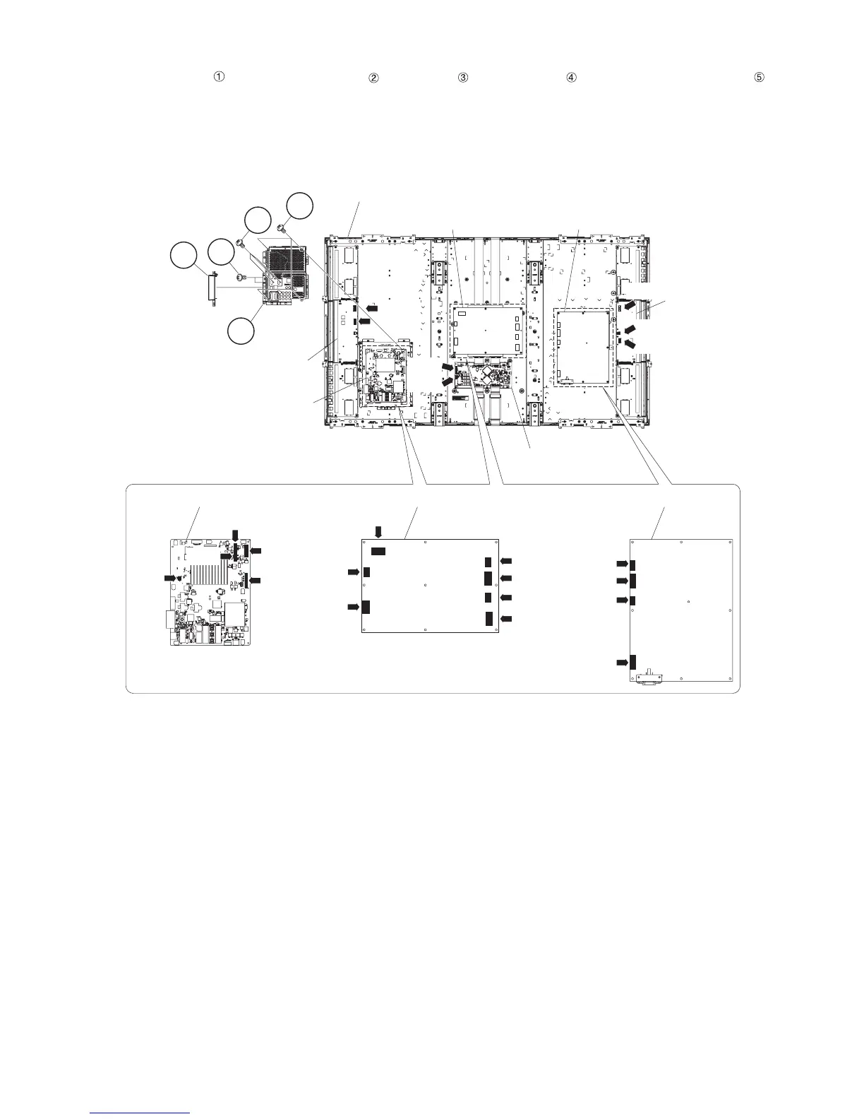
3. Removing of Connectors, Side Terminal Cover Ass’y, MAIN PWB Shield.
1. Remove the 3 lock screws , Side Terminal Cover Ass’y , 2 lock screws and 4 lock screws and detach the MAIN PWB Shield .
2. Disconnect the following connectors from the MAIN Unit. (LB1, PD, LW, LP, KM)
3. Disconnect the following connectors from the MAIN POWER Unit. (LA, PP1, PP2, PP3, PQ, PL, PD)
4. Disconnect the following connectors from the SUB POWER Unit. (PP1, PP2, PP3, PQ)
5. Disconnect the following connectors from the LCD Control Unit. (LW, FR)
4
1
3
2Side Terminal
Cover Ass'y
5MAIN PWB Shield
LCD Panel Module Unit Ass'y
LCD Control Unit
MAIN Unit
SUB POWER Unit
INVERTER-5 Unit
INVERTER-2 Unit
MAIN POWER Unit
[LC]
[LA2]
[LA1]
[LB]
[LC]
[LW]
[FR]
[PP2]
[PP1]
[PP3]
[PP1]
[PP2]
[PP3]
[PQ]
SUB POWER Unit
MAIN POWER Unit
[PQ]
[PL]
[PD]
[LA]
MAIN Unit
[LB1]
[KM]
[LP]
[PD]
[LW]
 Loading...