Do you have a question about the Sharp R-1505F and is the answer not in the manual?
| Brand | Sharp |
|---|---|
| Model | R-1505F |
| Category | Microwave Oven |
| Language | English |
Actions to take before commencing any service work on the oven.
Steps to take before starting any diagnostic or repair work.
Preparing the oven and equipment for microwave leakage measurement.
Performing the closed-door leakage test for microwave emissions.
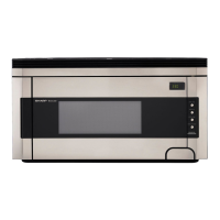
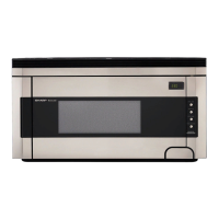
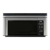
Overview of the microwave oven's features and capabilities.
General operational and safety information for the service technician.
Description of how the microwave oven functions during use.
Guidance for diagnosing and testing oven malfunctions.
Information and service procedures for the control panel assembly.
Detailed steps for replacing and adjusting oven components.
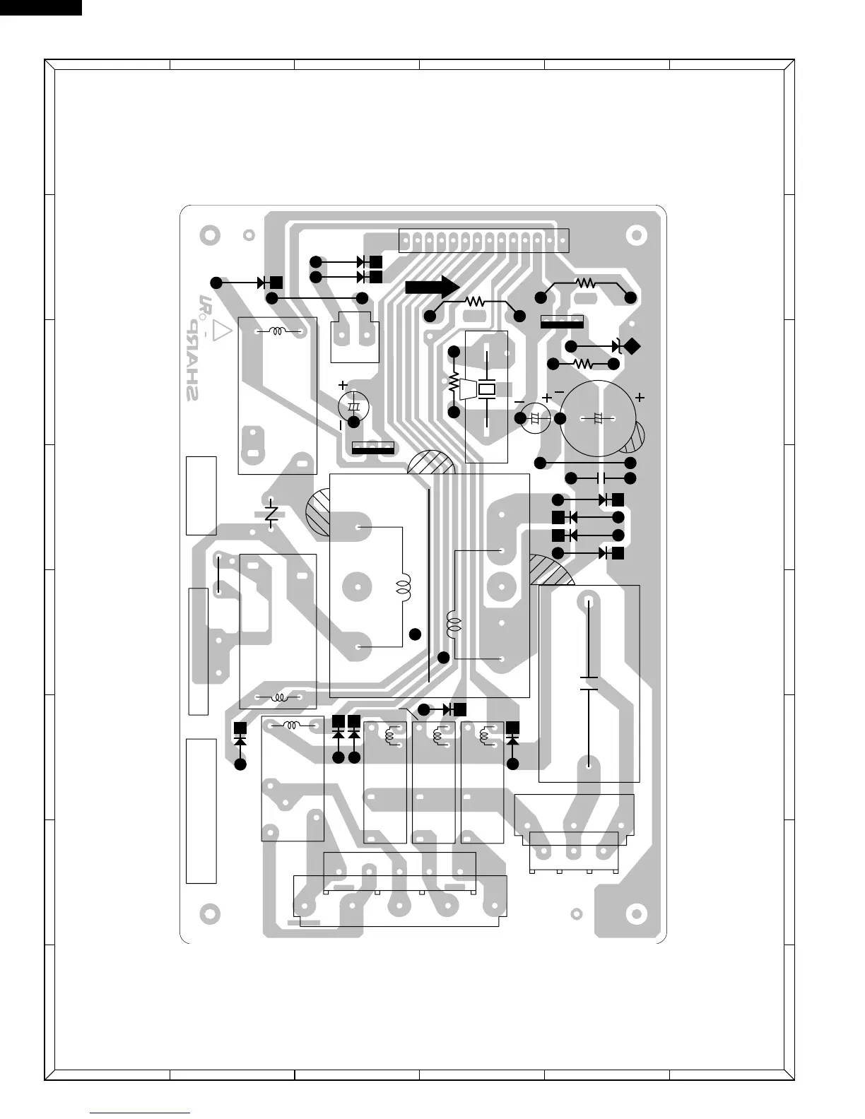
Visual representation of the oven's electrical connections.
Comprehensive list of all oven parts with part numbers.
Important operational and safety details, including grounding.
Step-by-step breakdown of the oven's functional sequence.
Details on variable power cooking levels and their timing.
How the door opening mechanism operates.
Function and interaction of door safety interlock switches.
Role and operation of the monitor switch in safety interlock system.
Function of the temperature fuse for magnetron protection.
Operation of the thermal cut-out for the hood fan motor.
Function of the thermal cut-out for the oven cavity.
How the turntable motor operates to ensure even cooking.
Function of the fan motor in cooling oven components.
Operation of the hood fan motor for ventilation.
Critical note regarding troubleshooting procedures and safety precautions.
Procedure to test the magnetron for proper operation.
Method for measuring microwave power output using a water test.
Procedure to test the power transformer's resistance and continuity.
Testing the high voltage rectifier for proper functionality.
Procedure for testing the high voltage capacitor's continuity and shorts.
Testing the thermal cut-out located within the oven cavity.
Testing the temperature fuse associated with the magnetron.
Testing the operation of the primary interlock switch.
Testing the door sensing switch and secondary interlock relay.
Procedure to test the monitor switch for correct operation.
Steps to diagnose and replace a blown monitor fuse.
Testing the thermal cut-out for the hood fan.
Procedure for testing the hood fan motor's operation and voltage.
Testing the touch control panel and its associated units.
Testing the key unit for proper pad response and signal output.
Diagnosing issues with the oven's main control unit.
Detailed steps to test the key unit for faults.
Detailed explanation of the Large Scale Integration (LSI) chip's I/O signals.
Safety measures for handling sensitive electronic parts like CMOS LSI.
Procedures and precautions for servicing the touch control panel.
Critical warnings about high voltage hazards during servicing.
Safety precautions to prevent electrical shock when working with wiring.
Steps to remove the hood exhaust louver assembly.
Procedure for safely removing the oven from its wall mounting.
Steps for removing the outer cabinet of the microwave oven.
Procedure for removing the power transformer component.
Steps to remove the hood fan motor.
Procedure for removing the magnetron from the oven.
Steps to remove the high voltage rectifier and capacitor.
Procedure for removing the hood fan thermal cut-out.
Steps to remove the thermal cut-out located in the oven cavity.
Procedure for removing the magnetron's temperature fuse.
Steps to remove the cooling fan motor.
Procedures for removing the turntable motor and hood lamp sockets.
Steps to remove the oven lamp and its socket.
Procedure for removing the positive lock connector.
Steps for removing the control panel and its associated units.
Procedure for removing door interlock and monitor switches.
Adjusting the door interlock and monitor switches for proper function.
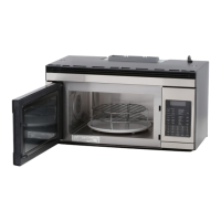
Procedures for the removal and re-installation of the oven door assembly.
Steps to remove the oven door assembly.
Steps for reinstalling the oven door assembly.
Detailed steps for disassembling the oven door components.
Procedure for removing the door's choke cover.
List of electrical components with part numbers and codes.
List of cabinet and external parts with part numbers.
List of parts related to the control panel assembly.
List of internal oven components and their part numbers.
List of parts specifically for the oven door assembly.
List of miscellaneous items including screws, hardware, and manuals.
Specific listing of screws, nuts, and washers used in the oven.
Instructions on how to correctly order replacement parts.
Information about packing materials and included accessories.
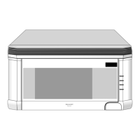
Illustrated breakdown of oven and cabinet parts with reference numbers.
Illustrated breakdown of control panel components.
Illustrated breakdown of oven door components.
Illustrated breakdown of miscellaneous parts.