EasyManua.ls Logo

Sharp R-1870 User Manual

Sharp R-1870
24 pages
To Next Page IconTo Next Page
To Previous Page IconTo Previous Page
Page #10 background imageLoading...
Page #10 background image
8
R-1870
R-1871
SCHEMATIC
NOTE: CONDITION OF OVEN
1. DOOR CLOSED.
2. CONVECTION PAD TOUCHED.
3. DESIRED TEMP. TOUCHED.
4. START PAD TOUCHED.
Figure O-3. Oven Schematic - Convection Cooking Condition (CONVEC, PREHEAT, BROIL, SLOW COOK)
SCHEMATIC
NOTE: CONDITION OF OVEN
1. DOOR CLOSED.
2. MIX COOKING PAD TOUCHED.
3. DESIRED TEMP. TOUCHED.
4. COOKING TIME PROGRAMMED.
5. START PAD TOUCHED.
Figure O-4. Oven Schematic - Automatic Mix cooking Condition
NOTE: RY2 and RY3 will alternately close during cook cycle
MAGNETRON
TEMPERATURE FUSE
RED
PN
K
BLK
GRY
GRY
GRY
BRN
BRN
PNK
GRY
DAMPER
MOTOR
FAN
MOTOR
TURNTABLE
MOTOR
CONVECTION
MOTOR
GRY
BLU
GRY
GRY
GRN
WHT
WHT
WHT
WHT
WHT
WHT
RED
PNK
WHT
RED
ORG
BLK
BLK
BLK
BLK
BLK BLK
BLK
MAGNETRON
BLK BLK
BRN
BRN
BRN
YLW
YLW
PPL
PPL
OVEN LAMP
HEATING
ELEMENT
MONITOR
SWITCH
STIRRER MOTOR
YLW
RED
BLU
WHT
BLK
BLK
BLK
BLK
BLK
AH SENSOR
POWER
TRANSFORMER
HIGH VOLTAGE
CAPACITOR
0.9F
HIGH VOLTAGE
RECTIFIER
COM.
RY1
COM.
RY2
COM.
RY3
N.O.
RY2
N.O.
RY1
N.O.
RY3
CONTROL UNIT
GND
GRN
BLU
PPL
HOOD
MOTOR
C3
C9
C5
C7
A1 A3 C1 A5 B5 B3 B1 B7
E1
E5 E6
E3
E4
E2
F1 F2 F3
DOOR
SENSING
SWITCH
DAMPER
SWITCHTHERMISTOR
SECONDARY
INTERLOCK
SWITCH
RED
YLW
GRY
WHT
WHT
120 V AC.
60 Hz
HOOD
LAMP
HL HL
DM
RY6 RY5 RY4 RY7 RY1
RY3
RY2
PRIMARY
INTERLOCK RELAY
FM
CM
OL
TTM
STM
BRN
HOOD FAN
THERMAL
CUT OUT
HOOD
CAPACITOR
RY9
RY10
RY8
FUSE
20A
BR
N
BLK
RESISTOR
NOISE
MAGNETRON
TEMPERATURE FUSE
RED
P
N
K
BLK
GRY
GRY
GRY
BRN
BRN
PNK
GRY
DAMPER
MOTOR
FAN
MOTOR
TURNTABLE
MOTOR
CONVECTION
MOTOR
GRY
BLU
GRY
GRY
GRN
WHT
WHT
WHT
WHT
WHT
WHT
RED
PNK
WHT
RED
ORG
BLK
BLK
BLK
BLK
BLK BLK
BLK
MAGNETRON
BLK BLK
BRN
BRN
BRN
YLW
YLW
PPL
PPL
OVEN LAMP
HEATING
ELEMENT
MONITOR
SWITCH
STIRRER MOTOR
YLW
RED
BLU
WHT
BLK
BLK
BLK
BLK
BLK
AH SENSOR
POWER
TRANSFORMER
HIGH VOLTAGE
CAPACITOR
0.9F
HIGH VOLTAGE
RECTIFIER
COM.
RY1
COM.
RY2
COM.
RY3
N.O.
RY2
N.O.
RY1
N.O.
RY3
CONTROL UNIT
GND
GRN
BLU
PPL
HOOD
MOTOR
C3
C9
C5
C7
A1 A3 C1 A5 B5 B3 B1 B7
E1
E5 E6
E3
E4
E2
F1 F2 F3
DOOR
SENSING
SWITCH
DAMPER
SWITCHTHERMISTOR
SECONDARY
INTERLOCK
SWITCH
RED
YLW
GRY
WHT
WHT
120 V AC.
60 Hz
HOOD
LAMP
HL HL
DM
RY6 RY5 RY4 RY7 RY1
RY3
RY2
PRIMARY
INTERLOCK RELAY
FM
CM
OL
TTM
STM
BRN
HOOD FAN
THERMAL
CUT OUT
HOOD
CAPACITOR
RY9
RY10
RY8
FUSE
20A
BR
N
BLK
RESISTOR
NOISE
Question and Answer IconNeed help?

Do you have a question about the Sharp R-1870 and is the answer not in the manual?

Sharp R-1870 Specifications

General IconGeneral
BrandSharp
ModelR-1870
CategoryMicrowave Oven
LanguageEnglish

Summary

Introduction and Safety Warnings

Model Identification and Overview

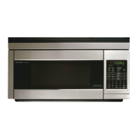
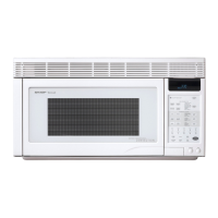
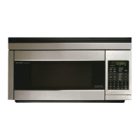
Identifies the microwave oven models covered by the manual.

Service Personnel High Voltage Warning

Warns service personnel about high voltage hazards within microwave ovens.

Microwave Exposure Prevention

Pre-Servicing Safety Checks

Outlines pre-service checks and actions for operative units.

Microwave Leakage Measurement Procedure

Details the setup and steps for conducting a microwave leakage test.

Critical Service Safety Procedures

High Voltage Component Hazards

Alerts service personnel to specific high-voltage parts to avoid.

Servicing and Testing Protocols

Provides step-by-step instructions for before, during, and after service testing.

Microwave Measurement Standards and Tests

Leakage Measurement Requirements

Specifies limits and standards for microwave leakage measurement.

Leakage Test Execution

Details the setup and steps for conducting a microwave leakage test.

Manual Scope and Operational Safety

Manual Purpose and Recommended Study

Explains the manual's purpose and recommends studying it with the base model manual.

Pre-Operation Safety Checklist

Lists critical checks to ensure oven safety before operation.

Specifications and Grounding

Technical Specifications Summary

Provides detailed technical specifications for the microwave oven.

Electrical Grounding Requirements

Explains the importance and procedure of proper grounding for safety.

Oven Diagrams and Control Panel

Oven Component Identification

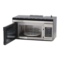
Illustrates the external and internal components of the oven.

Control Panel Layout and Buttons

Details the layout and function of the control panel buttons.

Oven Operation Sequences

Operating Mode Descriptions

Describes the sequence of operations for the oven (Off, Cooking).

Variable Power Cooking Levels

Explains the power level settings (P-0 to P-90) and their ON/OFF times.

Electrical Schematics Overview

Off Condition Circuit Diagram

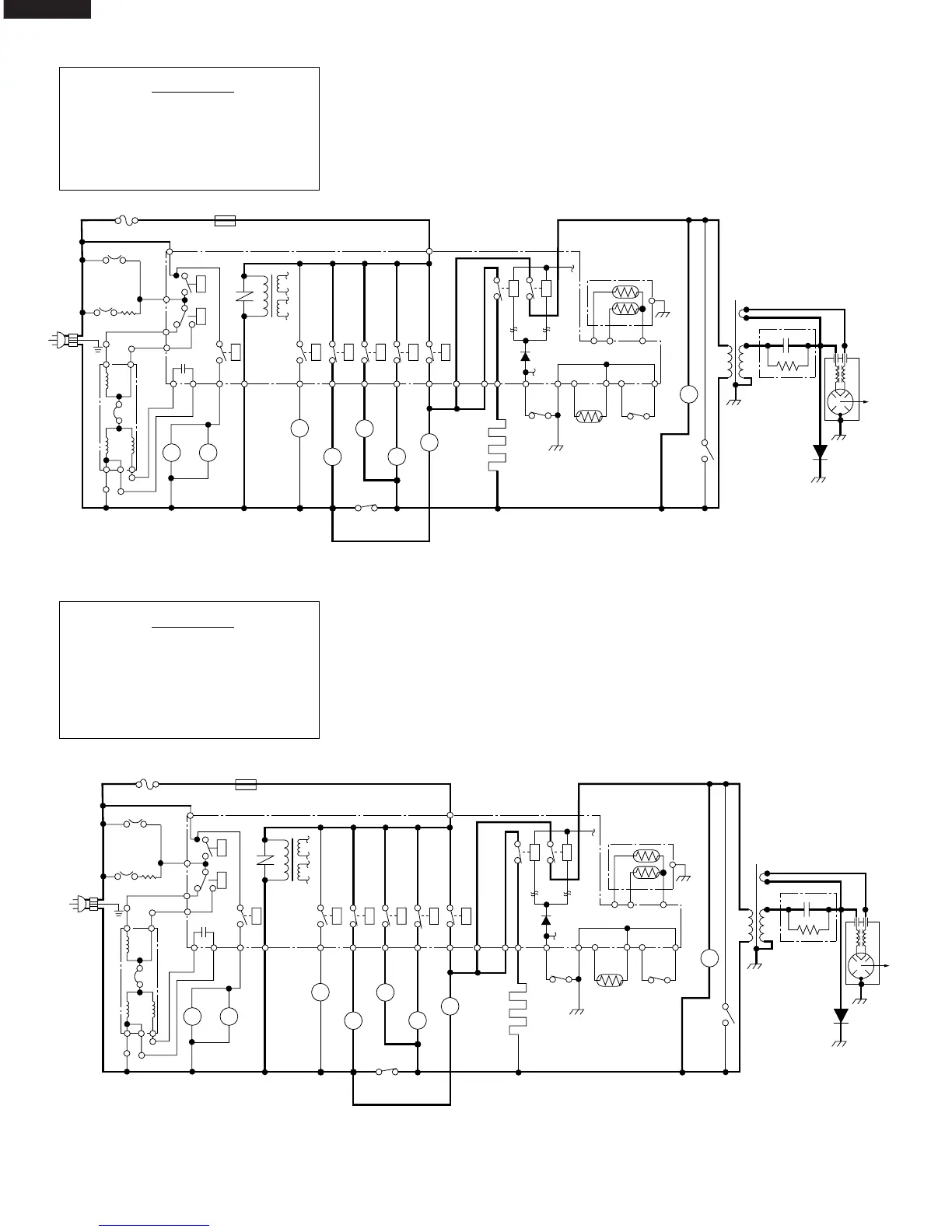
Illustrates the oven's electrical circuit in the off state.

Microwave Cooking Circuit Diagram

Shows the oven's electrical circuit during microwave cooking.

Specialized Operation Schematics

Convection Cooking Circuit

Depicts the electrical wiring for convection cooking modes.

Automatic Mix Cooking Circuit

Illustrates the circuit for automatic mixed cooking functions.

Component Testing

Key Unit Test Procedure

Describes how to test the key unit for proper functionality.

Pictorial Component Diagram

Oven Part Identification

Visually identifies various oven components in their locations.

Control Panel Circuitry

Touch Control Panel Schematic

Details the electrical circuit diagram for the touch control panel.

Parts Identification - Electrical and Cabinet

Electrical Parts List

Lists electrical parts, their part numbers, and quantities.

Cabinet Parts List

Lists cabinet parts, their part numbers, and quantities.

Parts Identification - Control Panel and Hardware

Control Panel Components

Lists parts related to the control panel and connectors.

Hardware and Fasteners List

Lists screws, nuts, and washers used in the assembly.

Oven and Cabinet Parts Diagram

Component Location Illustration

Visually identifies oven and cabinet components.

Parts Ordering and Hardware Details

Hardware Part Number List

Lists detailed part numbers for screws, nuts, and washers.

Procedure for Ordering Parts

Provides instructions on how to order replacement parts.

Packing and Accessories

Accessory Pack Contents List

Lists the items included in the accessory pack.

Packaging Material Overview

Illustrates the packing case and protective materials.

Assembly Diagrams

Control Panel Assembly View

Shows the assembly of control panel parts.

Door Assembly Components View

Illustrates the parts that make up the oven door.

Miscellaneous Parts Diagram

Depicts miscellaneous parts like harnesses and racks.

Related product manuals