R1900J
9 – 3
6. Remove the capacitor band from the high voltage capacitor.
7. Disconnect all wire leads from the high voltage capacitor.
8. Now, the capacitor (1) or (2) and the high voltage rectifier assembly
are free.
CAUTION: 1) DISCHARGE THE TWO HIGH VOLTAGE CAPACITOR
BEFORE TOUCHING ANY OVEN COMPONENTS OR
WIRING.
2) DO NOT REPLACE ONLY THE HIGH VOLTAGE REC-
TIFIER. IF IT IS DEFECTIVE, REPLACE THE HIGH
VOLTAGE RECTIFIER ASSEMBLY.
3) WHEN REPLACING THE HIGH VOLTAGE RECTIFIER
ASSEMBLY AND THE HIGH VOLTAGE CAPACITOR,
THE EARTH SIDE TERMINAL OF THE HIGH VOLT-
AGE RECTIFIER MUST BE SECURED FIRMLY WITH
A EARTHING SCREW.
[7] POWER SUPPLY CORD REPLACEMENT
1. REMOVAL
1. CARRY OUT 3D CHECKS.
2. Remove the rear cover.
3. Remove the one (1) screw holding the earth wire of the power sup-
ply cord to the oven cavity.
4. Disconnect the wire leads of the power supply cord from the noise
filter.
5. Remove the one (1) screw holding the power supply cord angle to
the capacitor unit angle.
6. Remove the power supply cord angle with the power supply cord
from the capacitor unit angle.
7. Nip the cord bushing with the bushing pliers and release it from the
power supply cord angle.
8. Remove the cord bushing with the power supply cord from the
power supply cord angle.
9. Remove the cord bushing from the power supply cord.
10.Now, the power supply cord is free.
2. INSTALLATION
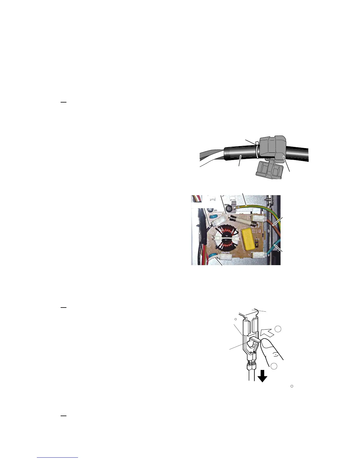
1. Install the cord bushing to the power supply cord so that the lock tie
on the power supply cord surface comes to the end of the cord
bushing as shown in the.Figure C-2.
2. Install the cord bushing (with the power supply cord) into the hole of
the power supply cord angle with the bushing pliers.
3. Reinstall the power supply cord angle to the capacitor unit angle
with the one (1) screw.
4. Install the earth wire of the power supply cord to the oven cavity
with the one (1) screw.
5. Connect the brown wire lead of the power supply cord to the source
side upper terminal of the noise filter.
6. Connect the blue wire lead of the power supply cord to the source
side lower terminal of the noise filter.
7. Reinstall the rear cover, the magnetron exhaust cover and the
outer case cabinet and check that the oven is operating properly.
Figure C-2(a) Cord bushing position
Figure C-2(b) Wiring to the noise filter
[8] HOW TO RELEASE THE POSITIVE LOCK CONNECTOR.
1. CARRY OUT 3D CHECKS.
2. Push the lever of positive lock connector, pull down the connector
from terminal.
3. Now, the connector is free.
CAUTION: THE POSITIVE LOCKR TERMINAL CAN NOT BE
REMOVED BYJUST PULLING ON IT. THE LOCK LEVER
MUST BE RELEASED TO REMOVE THE CONNECTOR
FROM THE TERMINAL.
[9] EXHAUST FAN REMOVAL
1. CARRY OUT 3D CHECKS.
2. Remove the rear cover.
3. Make sure that the connector of the exhaust fan has been discon-
nected from the wire harness.
4. Remove the four (4) screws and the two (2) nuts holding the
exhaust fan.
5. Now, the exhaust fan is free.
 Loading...