6
R-200BK
R-200BW
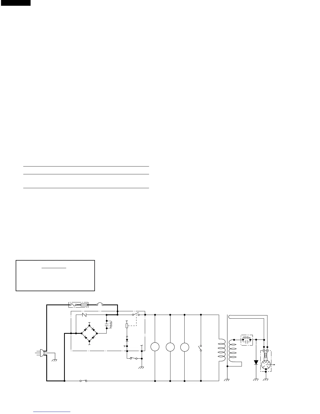
SCHEMATIC
NOTE: CONDITION OF OVEN
1. LIGHT UP DIAL OFF.
2. DOOR CLOSED.
OPERATION
DESCRIPTION OF OPERATING SEQUENCE
The following is a description of component functions during
oven operation.
OFF CONDITION
Closing the door activates door sensing switch and second-
ary interlock switch. (In this condition, the monitor switch
contacts are opened.)
When oven is plugged in, 120 volts A.C. is supplied to the
control unit. (Figure O-1).
COOKING CONDITION
When the Light Up Dial is turned, the following operations
occur:
1. The contacts of the relay are closed and components
connected to the relay are turned on as follows.
(For details, refer to Figure O-2)
RELAY CONNECTED COMPONENTS
RY-1 oven lamp/turntable motor/fan motor
power transformer
2. 120 volts A.C. is supplied to the primary winding of the
power transformer and is converted to about 3.5 volts
A.C. output on the filament winding, and approximately
2000 volts A.C. on the high voltage winding.
3. The filament winding voltage heats the magnetron
filament and the H.V. winding voltage is sent to a voltage
doubler circuit.
4. The microwave energy produced by the magnetron is
channelled through the waveguide into the cavity feed-
box, and then into the cavity where the food is placed to
be cooked.
5. Upon completion of the cooking time, the power
transformer, oven lamp, etc. are turned off, and the
generation of microwave energy is stopped. The oven
will revert to the OFF condition.
6. When the door is opened during a cook cycle, monitor
switch, door sensing switch, secondary interlock switch
and primary interlock relay (RY1) are activated with the
following results. The circuits to the oven lamp, turntable
motor, the cooling fan motor, and the high voltage
components are de-energized, and the Light Up Dial
indicates the time still remaining in the cook cycle when
the door was opened.
7. The monitor switch is electrically monitoring the operation
of the primary interlock relay (RY1) and the secondary
interlock switch and is mechanically associated with the
door so that it will function in the following sequence.
(1) When the door opens from the closed position, the
secondary interlock switch, door sensing switch and
primary interlock relay (RY1) open their contacts. Then
the monitor switch contacts close.
(2) When the door is closed from the open position, the
monitor switch contacts open first. Then the contacts
of the secondary interlock switch and door sensing
switch close.
If the secondary interlock switch and primary interlock relay
(RY1) fail with the contacts closed when the door is opened,
the closing of the monitor switch contacts will form a short
circuit through the C/T fuse and primary interlock relay
(RY1), causing the C/T fuse to blow.
Figure O-1. Oven Schematic-Off Condition
POWER
TRANSFORMER
RECTIFIER
MAGNETRON
CAPACITOR
0.72µF
C/T FUSE
120V AC
60 Hz
TURN-
TABLE
MOTOR
FAN
MOTOR
MONITOR
SWITCH
SECONDARY
INTERLOCK
SWITCH
TTM
OVEN
LAMP
OL
FM
A3
COM.
N.O.
DOOR
SENSING
SWITCH
A1 A3
(RY-1)
CONTROL UNIT
PRIMARY
INTERLOCK
RELAY
MAGNETRON
THERMAL CUT-OUT
 Loading...