7
R-203CW
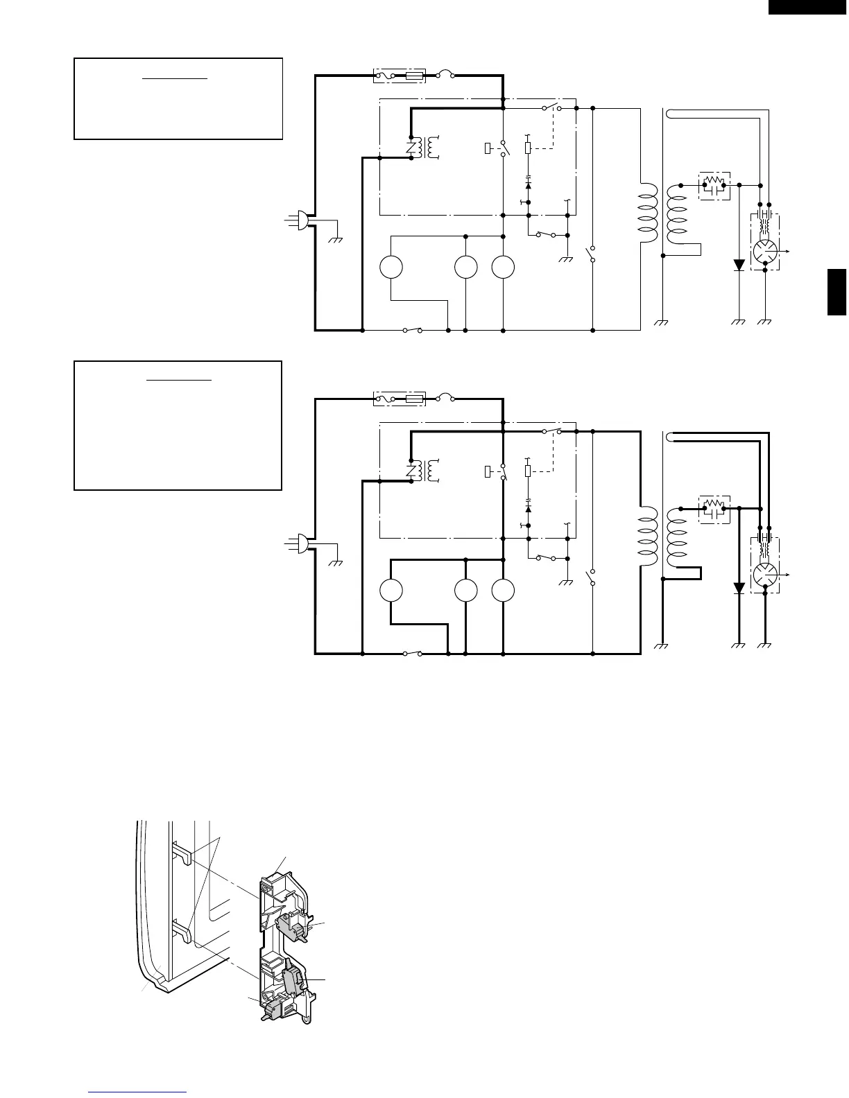
Figure O-1. Oven Schematic-Off Condition
SCHEMATIC
NOTE: CONDITION OF OVEN
1. DOOR CLOSED
2. CLOCK APPEARS ON DISPLAY
SCHEMATIC
NOTE: CONDITION OF OVEN
1. DOOR CLOSED
2. COOKING TIME PROGRAMMED
3. VARIABLE COOKING CONTROL
"HIGH"
4. "START" PAD TOUCHED
Figure O-2. Oven Schematic-Cooking Condition
POWER
TRANSFORMER
RECTIFIER
MAGNETRON
CAPACITOR
0.86µF
C/T FUSE
120V AC
60 Hz
OVEN
LAMP
TURN-
TABLE
MOTOR
FAN
MOTOR
MONITOR
SWITCH
SECONDARY
INTERLOCK
SWITCH
TTM
OL FM
GRN
A3
COM.
N.O.
DOOR
SENSING
SWITCH
B1 B2
(RY-1)
(RY-2)
CONTROL UNIT
PRIMARY
INTERLOCK
RELAY
MAGNETRON
THERMAL CUT-OUT
A1
POWER
TRANSFORMER
RECTIFIER
MAGNETRON
CAPACITOR
0.86µF
C/T FUSE
120V AC
60 Hz
OVEN
LAMP
TURN-
TABLE
MOTOR
FAN
MOTOR
MONITOR
SWITCH
SECONDARY
INTERLOCK
SWITCH
TTM
OL FM
GRN
A3
COM.
N.O.
DOOR
SENSING
SWITCH
B1 B2
(RY-1)
(RY-2)
CONTROL UNIT
PRIMARY
INTERLOCK
RELAY
MAGNETRON
THERMAL CUT-OUT
A1
DESCRIPTION AND FUNCTION OF COMPONENTS
DOOR OPEN MECHANISM
The door is opened by pulling the door, refer to the Figure
D-1.
Latch Heads
Latch Hook
Door
Door
Sensing
Switch
Monitor
Switch
Secondary
Interlock
Switch
Figure D-1. Door Open Mechanism
DOOR SENSING AND SECONDARY INTERLOCK
SWITCHES
The secondary interlock switch is mounted in the lower
position of the latch hook and the door sensing switch in the
primary interlock system is mounted in the upper position of
the latch hook. They are activated by the latch heads on the
door. When the door is opened, the switches interrupt the
power to all high voltage components. A cook cycle cannot
take place until the door is firmly closed thereby activating
both interlock switches. The primary interlock system con-
sists of the door sensing switch and primary interlock relay
located on the control circuit board.
MONITOR SWITCH
The monitor switch is activated (the contacts opened) by the
latch head on the door while the door is closed. The switch
is intended to render the oven inoperative, by means of
 Loading...