6
R-209FK
R-209FW
TEST PROCEDURES
PROCEDURE
LETTER
COMPONENT TEST
B POWER TRANSFORMER TEST
1. Disconnect the power supply cord, and then remove outer case.
2. Open the door and block it open.
3. Discharge high voltage capacitor.
4. Disconnect the primary input terminals and measure the resistance of the transformer with an
ohmmeter. Check for continuity of the coils with an ohmmeter. On the R x 1 scale, the resistance of
the primary coil should be less than 1 ohm and the resistance of the filament coil should be less than
1 ohm. And the resistance of the high voltage coil should be obtained in the table below.
Part number of power transformer Resistance of the high voltage coil
RTRN-A672WRZZ Approx. 144 Ω
RTRN-A675WRZZ Approx. 157 Ω
RTRN-A646WRZZ Approx. 132 Ω
5. Reconnect all leads removed from components during testing.
6. Reinstall the outer case (cabinet).
7. Reconnect the power supply cord after the outer case is installed.
8. Run the oven and check all functions.
(HIGH VOLTAGES ARE PRESENT AT THE HIGH VOLTAGE TERMINAL, SO DO NOT ATTEMPT TO
MEASURE THE FILAMENT AND HIGH VOLTAGE.)
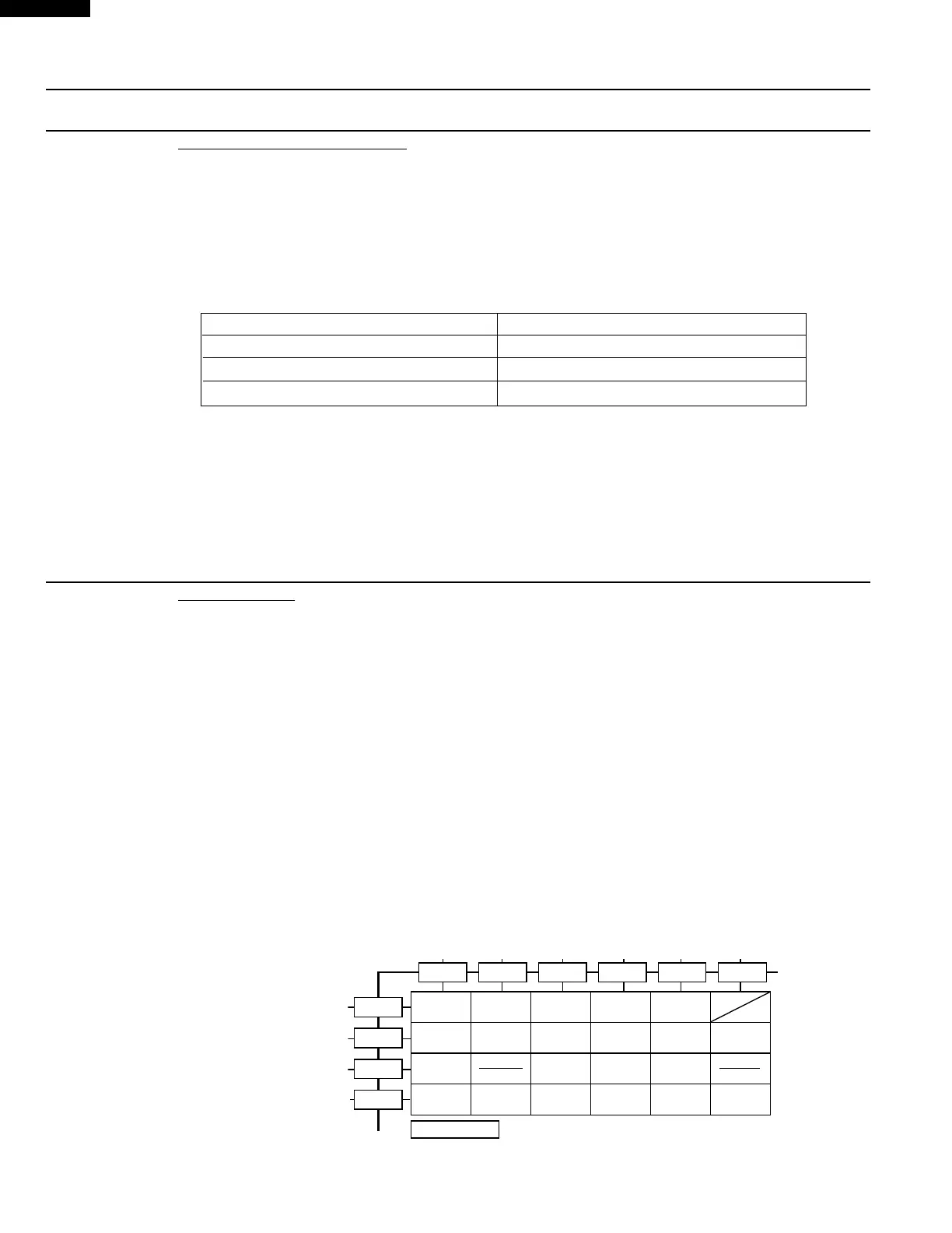
J KEY UNIT TEST
1. Disconnect the power supply cord and then remove outer case.
2. Open the door and block it open.
3. Discharge high voltage capacitor.
4. If the display fails to clear when the STOP/CLEAR pad is depressed, first verify the flat ribbon cable
is making good contact, verify that the door sensing switch operates properly; that is the contacts are
closed when the door is closed and open when the door is open. If the door sensing switch is good,
disconnect the flat ribbon cable that connects the key unit to the control unit and make sure the door
sensing switch is closed (either close the door or short the door sensing switch connector). Use the
Key unit matrix indicated on the control panel schematic and place a jumper wire between the pins
that correspond to the STOP/CLEAR pad making momentary contact. If the control unit responds by
clearing with a beep the key unit is faulty and must be replaced. If the control unit does not respond,
it is faulty and must be replaced. If a specific pad does not respond, the above method may be used
(after clearing the control unit) to determine if the control unit or key pad is at fault.
5. Reconnect all leads removed from components during testing.
6. Re-install the outer case (cabinet).
7. Reconnect the power supply cord after the outer case is installed.
8. Run the oven and check all functions.
G10
G 9
G 8
G 7
G 6 G 5 G 4 G 3 G 2 G 1
FRESH
VEGETABLES
POWER
LEVEL
STOP
CLEAR
ROLLS
MUFFINS
DINNER
PLATE
MINUTE
PLUS
BAKED
POTATOES
START
EXPRESS
DEFROST
POPCORN
BEVERAGE
6
3
9
2
5
0
8
4
1
7
KEY UNIT
TIMER
CLOCK
FROZEN
ENTREES
 Loading...