R21LCF
8 – 5
When testing is completed,
1) Disconnect the power supply cord and then remove outer case.
2) Open the door and block it open.
3) Discharge high voltage capacitor.
4) Reconnect all leads removed from components during testing.
5) Re-install the outer case (cabinet).
6) Reconnect the power supply cord after the outer case is installed.
7) Run the oven and check all functions.
[12] Procedure L: RELAY TEST
1. Disconnect the power supply cord, and then remove outer case.
2. Open the door and block it open.
3. Discharge high voltage capacitor.
4. Disconnect the leads to the primary of the power transformer.
5. Ensure that these leads remain isolated from other components and oven chassis by using insulation tape.
6. After that procedure, re-connect the power supply cord.
7. Remove the outer case and check voltage between Pin No. 5 of the 3 pin connector (A) and the common terminal of the relay RY1 on the control
unit with an A.C. voltmeter.
The meter should indicate 120 volts, if not check oven circuit.
RY1 and RY2 Relay Test
These relays are operated by D.C. voltage
Check voltage at the relay coil with a D.C. voltmeter during the microwave cooking operation.
DC. voltage indicated ................. Defective relay.
DC. voltage not indicated ........... Check diode which is connected to the relay coil. If diode is good, control unit is defective.
NOTE: The voltage under the condition when all LEDs light up.
8. Disconnect the power supply cord and then remove outer case.
9. Open the door and block it open.
10.Discharge high voltage capacitor.
11. Reconnect all leads removed from components during testing.
12.Re-install the outer case (cabinet).
13.Reconnect the power supply cord after the outer case is installed.
14.Run the oven and check all functions.
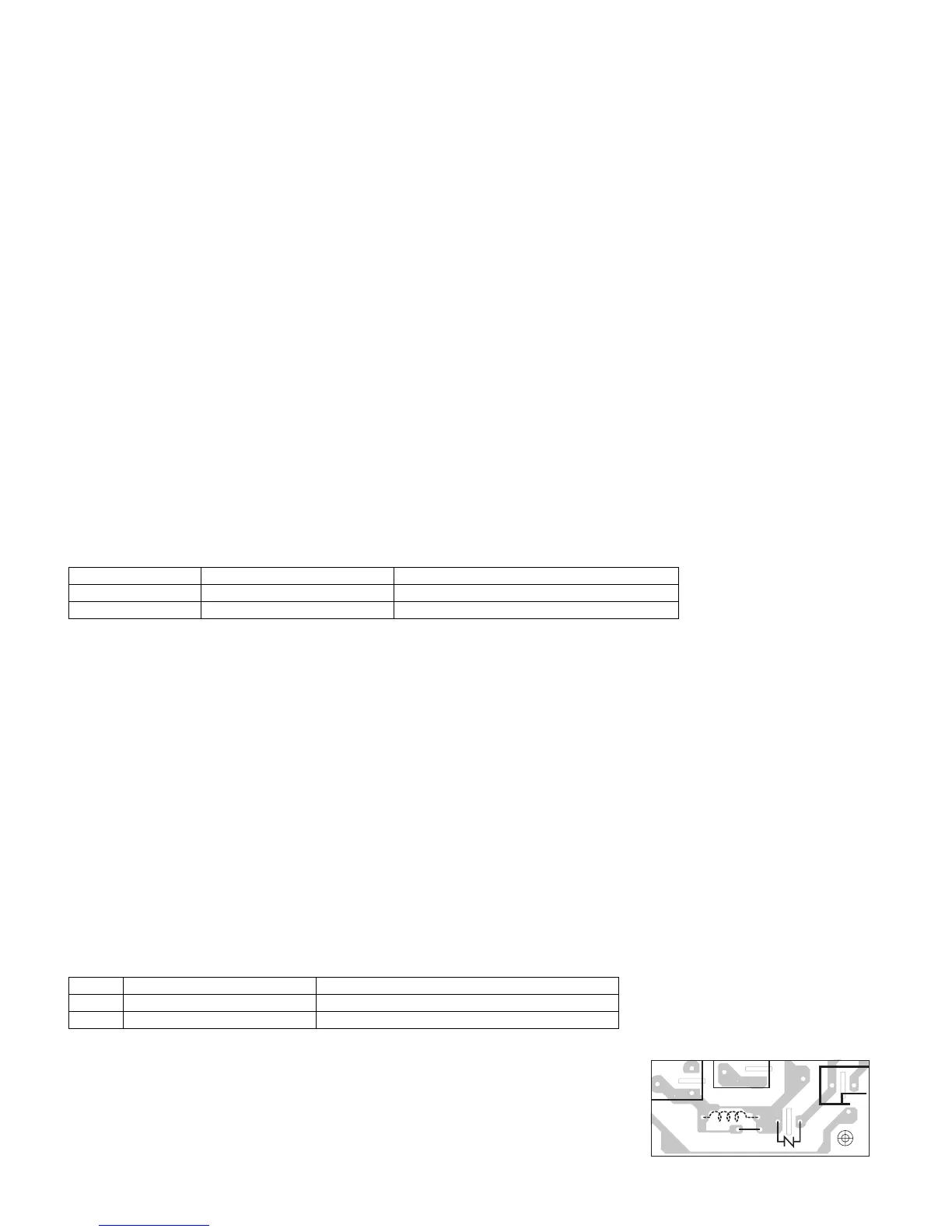
[13] Procedure M: FOIL PATTERN ON THE PRINTED WIRING BOARD TEST
To protect the electronic circuits, this model is provided with a fine foil pattern added to the primary on the PWB, this foil pattern acts as a fuse.
1. Foil pattern check and repairs.
1) Disconnect the power supply cord and then remove outer case.
2) Open the door and block it open.
3) Discharge high voltage capacitor.
4) Follow the troubleshooting guide given below for repair.
5) Make a visual inspection of the varistor. Check for burned damage.
6) Reconnect all leads removed from components during testing.
7) Re-install the outer case (cabinet).
8) Reconnect the power supply cord after the outer case is installed.
9) Run the oven and check all functions.
RELAY SYMBOL OPERATIONAL VOLTAGE CONNECTED COMPONENTS
RY1 Approx. 19.2V D.C. Oven lamp / Antenna motor / Cooling fan motor
RY2 Approx. 19.9V D.C. Power transformer
STEPS OCCURRENCE CAUSE OR CORRECTION
1 Only pattern at “a” is broken. *Insert jumper wire J1 and solder.
2 Pattern at “a” and “b” are broken. *Replace control unit.
 Loading...