20
R-220DW
R-230DK
R-230DW
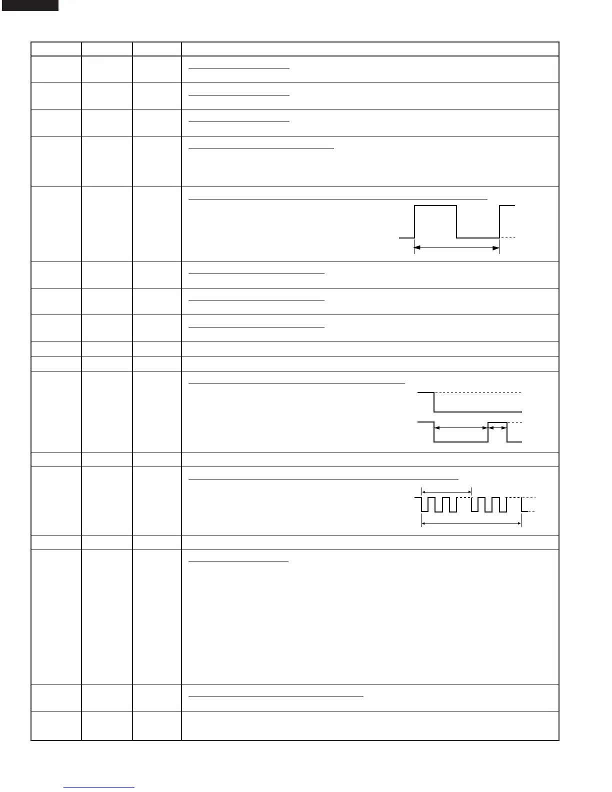
Pin No. Signal I/O Description
23 P23 IN Signal similar to K02.
When either G7 line on key matrix is touched, a corresponding signal will be input into P23.
24 K00 IN Signal similar to K02.
When either G8 line on key matrix is touched, a corresponding signal will be input into K00.
25 K01 IN Signal similar to K02.
When either G9 line on key matrix is touched, a corresponding signal will be input into K01.
26 K02 IN Signal coming from touch key.
When either G10 line on key matrix is touched, a corresponding signal out of R00, R01,
R02, R03, P20 and P21 will be input into K02. When no key is touched, the signal is
held at “H” level.
27 K03 IN Signal synchronized with commercial power source frequency.
This is the basic timing for time processing of
LSI.
28 COM0 OUT Common data signal: COM1.
Connected to LCD (Pin No. C1)
29 COM1 OUT Common data signal: COM2.
Connected to LCD (Pin No. C2)
30 COM2 OUT Common data signal: COM1.
Connected to LCD (Pin No. C3)
31 COM3 OUT Terminal not used.
32-33 SEG0-SEG1 OUT Terminal not used.
34 SEG2 OUT Magnetron high-voltage circuit driving signal.
To turn on and off the cook relay (RY2).
The signals holds “L” level during micro-
wave cooking and “H” level while not cook-
ing. In other cooking modes (variable cook-
ing) the signal turns to “H” level and “L” level
in repetition according to the power level.
35 SEG3 OUT Terminal not used.
36 SEG4 OUT Oven lamp, fan motor and turntable motor driving signal.
To turn on and off shut off relay (RY1). The
square waveform voltage is delivered to
the RY1 driving circuit and RY2 control
circuit.
37-39
SEG5-SEG7
OUT Terminal not used.
40-51
SEG8-SEG19
OUT Segment data signal.
Connected to LCD.
The relation between signals are as follows:
LSI signal (Pin No.) LCD (Pin No.) LSI signal (Pin No.) LCD (Pin No.)
SEG 8 (40) .......................... S12 SEG 14 (46)........................... S6
SEG 9 (41) .......................... S11 SEG 15 (47)........................... S5
SEG 10 (42) .......................... S10 SEG 16 (48)........................... S4
SEG 11 (43) ............................ S9 SEG 17 (49)........................... S3
SEG 12 (44) ............................ S8 SEG 18 (50)........................... S2
SEG 13 (45) ............................ S7 SEG 19 (51)........................... S1
52-53 VC1-VC2 IN Power source voltage input terminal.
Standard voltage for LCD.
54 VC3 OUT Terminal not used.
GND
-5V
16.7 msec.
H : GND
L : -5V
OFF
ON
ON
OFF
OFF
H : GND
L : -5V
100P
70P
24 sec.
8 sec.
During cooking
L : -5V
H : GND
16.7 msec.
 Loading...