R-22GT-F
R-22GV-F
5
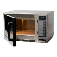
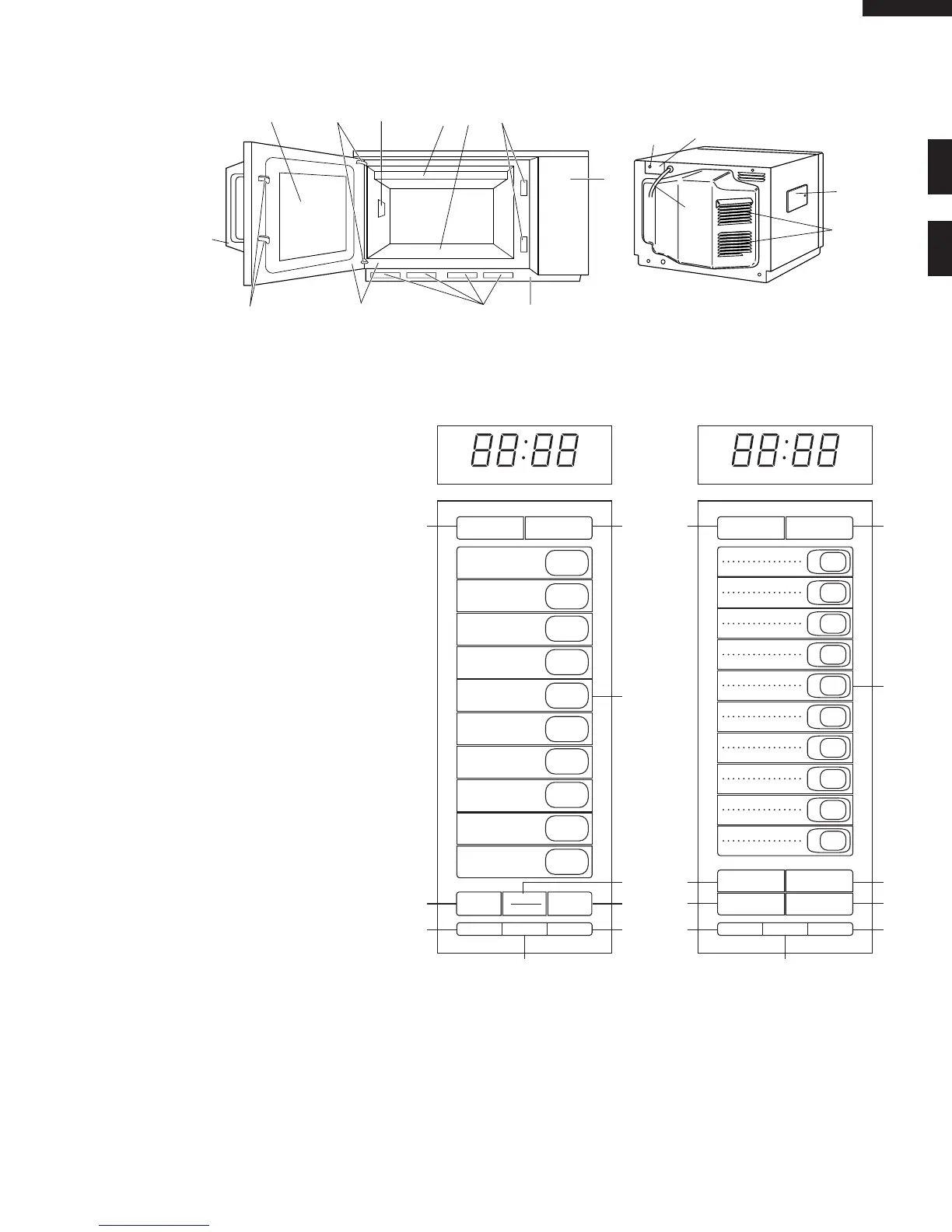
OVEN DIAGRAM
1. Touch control panel
2. Door latch openings
3. Ceramic shelf
4. Splash cover
5. Oven light
6. Air intake filter
7. Air intake openings
8. Door seals and sealing surfaces
9. Door hinges
10.Oven door with see-through window
11.Door latches
12.Door handle
13.Service window for replacing the oven
light bulb.
14.Ventilation openings
15.Power supply cord
16.Mounting plate
17.Screw for mouning plate
Control Panel
18.DOUBLE QUANTITY pad
19.EXPRESS DEFROST pad
20.Ten number pads for time and memory
programming
21.SELECTATIME pad
22.STOP/CLEAR pad; touch to stop
operation of oven and clear remaining
heating time
23.SELECTAPOWER pad for setting
variable power level
24.START pad; touch to operate oven after
door is closed and time is set
25.SET pad for setting memory
26.CHECK pad for checking memory
27.SIGNAL pad for setting signal sound
4
1
5
2
9
3
678
10
11
12
15
14
13
16
17
DOUBLE
QUANTITY
EXPRESS
DEFROST
1
2
3
4
5
6
7
8
9
0
SELECTA
TIME
STOP
CLEAR
START
SET CHECK SIGNAL
DEF
ON
NO.
X2
CHECK
19
20
22
24
27
25
21
18
26
DOUBLE
QUANTITY
EXPRESS
DEFROST
1
11
2
12
3
13
4
14
5
15
6
16
7
17
8
18
9
19
0
20
SELECTATIME STOP/CLEAR
SELECTAPOWER
START
SET CHECK SIGNAL
DEF
ON
NO.
X2
CHECK
19
20
22
24
27
25
23
21
18
26
R-22GV-F R-22GT-F
 Loading...