14
R-310AK
R-330AK
R-330AW
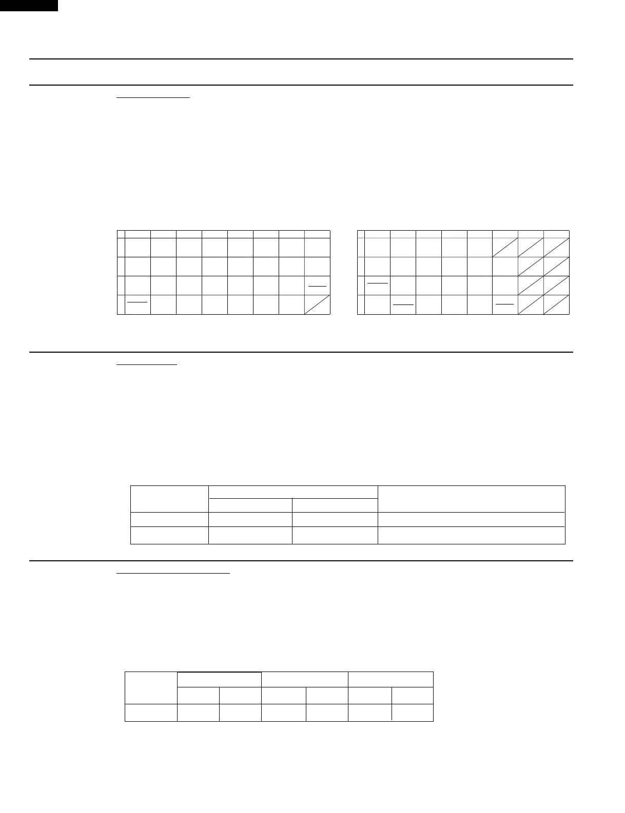
K KEY UNIT TEST
TEST PROCEDURES
PROCEDURE
LETTER
COMPONENT TEST
If the display fails to clear when the STOP/CLEAR pad is depressed, first verify the flat ribbon is making
good contact, verify that the door sensing switch (stop switch) operates properly; that is the contacts are
closed when the door is closed and open when the door is open. If the door sensing switch (stop switch)
is good, disconnect the flat ribbon cable that connects the key unit to the control unit and make sure the
door sensing switch is closed (either close the door or short the door sensing switch connecter). Use the
Key unit matrix indicated on the control panel schematic and place a jumper wire between the pins that
correspond to the STOP/CLEAR pad making momentary contact. If the control unit responds by clearing
with a beep the key unit is faulty and must be replaced. If the control unit does not respond, it is a faulty
and must be replaced. If a specific pad does not respond, the above method may be used (after clearing
the control unit) to determine if the control unit or key pad is at fault.
54321
09876
STOP
CLEAR
MINUTE
PLUS
FRESH VEG
SOFT
FRESH VEG
HARD
COMPU
COOK
COMPU
DEFROST
FISH
SEA FOOD
POWER
LEVEL
CUSTOM
HELP
CLOCK
SOUP
REHEAT
RICE
POPCORN
KITCHEN
TIMER
FROZEN
VEG
FROZEN
DINNER
BAKED
POTATO
GROUND
MEAT
HOT
DOG
START
TOUCH
ON
G 8 G 7 G 6 G 5 G 4 G 3 G 2 G 1
G12 G11 G10 G 9
54321
09876
STOP
CLEAR
TIMER
CLOOK
REHEAT
CASSEROLE
FRESH
VEGETABLE
COMPU
DEFROST
POWER
LEVEL
POPCORN
BEVERAGE
DINNER
PLATE
FRESH
ROLL
/ MUFFIN
FROZEN
ROLL
/ MUFFIN
START
MINUTE
PLUS
BAKED
POTATO
G 8 G 7 G 6 G 5 G 4 G 3 G 2 G 1
G12 G11 G10 G 9
R-330AK/AW R310AK
Remove the outer case and check voltage between Pin No. 3 of the 2 pin connector (A) and the common
terminal of the relay RY2 on the control unit with an A.C. voltmeter.
The meter should indicate 120 volts, if not check oven circuit.
RY1 and RY2 Relay Test
These relays are operated by D.C. voltage
Check voltage at the relay coil with a D.C. voltmeter during the microwave cooking operation.
DC. voltage indicated ............. Defective relay.
DC. voltage not indicated ........ Check diode which is connected to the relay coil. If diode is good, control
unit is defective.
RELAY SYMBOL
OPERATIONAL VOLTAGE
CONNECTED COMPONENTS
R-330AK/AW R-310AK
RY1 Approx. 24.0V D.C. Approx. 15.5V D.C. Oven lamp / Turntable motor / Cooling fan motor
RY2 Approx. 23.0V D.C. Approx. 12.0V D.C. Power transformer
L RELAY TEST
(1) Place one cup of water in the center of the turntable tray in the oven cavity.
(2) Close the door, touch the “ COMPU DEFROST “ pad twice and touch the Number pad “5”. And then
touch the “START” pad. (for R-310AK)
Close the door, touch the “ COMPU DEFROST “ pad and touch the Number pad “2”, and touch
Number pad “5”. And then touch the “START” pad. (for R-330AK/AW)
(3) The oven is in Compu Defrost cooking condition.
(4) The oven will operate as follows
WEIGHT
1ST STAGE 2ND STAGE 3RD STAGE
LEVEL TIME LEVEL TIME LEVEL TIME
0.5lbs 70% 40sec. 50% 38sec. 30% 43sec.
(5) If improper operation is indicated, the control unit is probably defective and should be checked.
M COMPU DEFROST TEST
 Loading...