21
R-330DK
R-330DW
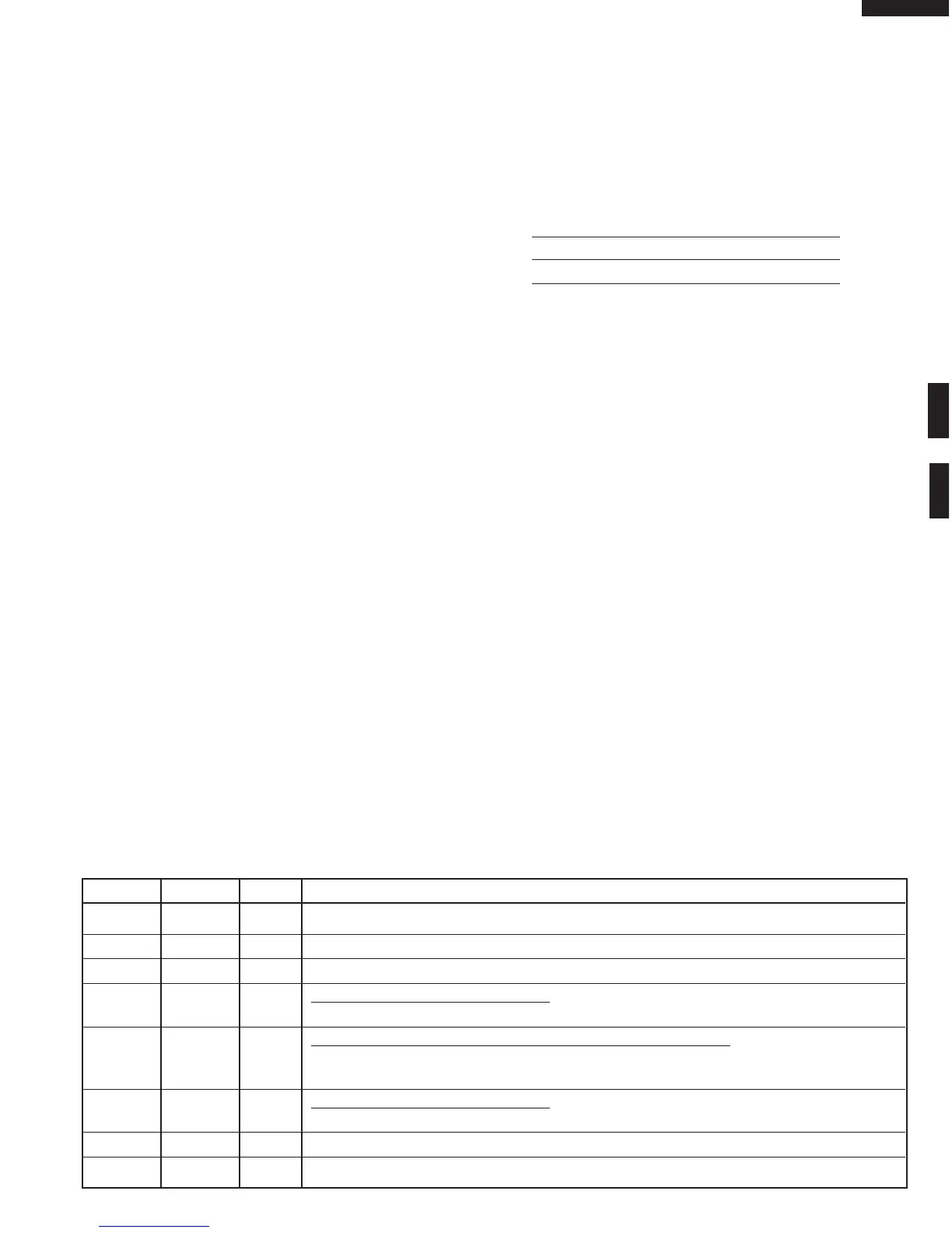
1-2 P26-P27 OUT Terminal not used.
3-5 P70-P72 OUT Terminal not used.
6 IC IN Connected to VC.
7 X2 OUT Internal clock oscillation output.
Output to control oscillation input to X2.
8X1INInternal clock oscillation frequency control input setting.
The internal clock frequency is set by inserting the ceramic filter oscillation circuit with
respect to X1.
9 VDD1 IN Power source voltage: GND(0V).
The power source voltage to drive LSI is input to VDD1 terminal.
10 XT1 IN Connected to GND.
11 XT2 OUT Terminal not used.
TOUCH CONTROL PANEL ASSEMBLY
OUTLINE OF TOUCH CONTROL PANEL
The touch control section consists of the following units.
(1) Key Unit
(2) Control Unit (The Control Unit consists of Power Unit
and LSI Unit).
The principal functions of these units and the signals com-
municated among them are explained below.
Key Unit
The key unit is composed of a matrix, signals generated in
the LSI are sent to the key unit through P110-P117.
When a key pad is touched, a signal is completed through
the key unit and passed back to the LSI through P100, P101,
P102, P103, ANI6 and ANI7 to perform the function that was
requested.
Control Unit
Control unit consists of LSI, ACL circuit, indicator circuit,
power source circuit, relay circuit, buzzer circuit, synchro-
nizing signal circuit, absolute humidity sensor circuit and
back light circuit.
1) ACL
This circuit generates a signal which resets the LSI to the
initial state when power is supplied.
2) Indicator Circuit
This circuit consists of 40 segments and 16 common
electrodes using a Liquid Crystal Display. The Liquid
Crystal Display (LCD) is drived by LCD driver IC3.
3) Power Source Circuit
This circuit generates voltages necessary in the control
unit from the AC line voltage.
In addition, the synchronizing signal is available in order
to compose a basic standard time in the clock circuit.
Symbol Voltage Application
VC -5V LSI(IC1)
4) Relay Circuit
A circuit to drive the magnetron, fan motor, turntable
motor and light the oven lamp.
5) Buzzer Circuit
The buzzer is responsive to signals from the LSI to emit
audible sounds (key touch sound and completion sound).
6) Synchronizing Signal Circuit
The power source synchronizing signal is available in
order to compose a basic standard time in the clock
circuit. It accompanies a very small error because it
works on commercial frequency.
7) Door Sensing Switch
A switch to “tell” the LSI if the door is open or closed.
8) Back Light Circuit
A circuit to drive the back light (Light emitting diodes
LD10- LD19).
9) Absolute Humidity Sensor Circuit
This circuit detects moisture of the cooking food to allow
its automatic cooking.
Pin No. Signal I/O Description
LSI(IXA037DR)
The I/O signal of the LSI(IXA037DR) is detailed in the following table.
 Loading...