22
R-3A56
FAN MOTOR REPLACEMENT
REMOVAL
1. CARRY OUT 3D CHECKS.
2. Disconnect the wire leads from the fan motor and thermal
cut-out.
3. Remove the three (3) screws holding the fan motor
assembly to the oven cavity.
4. Release the fan duct assembly from the oven cavity.
5 Remove one (1) screw from the thermal cut-out angle.
6. Remove the fan motor assembly from the oven cavity.
7. Remove the fan blade from the fan motor shaft according
the following procedure.
1) Hold the edge of the rotor of the fan motor by using a pair
of grove joint pliers.
CAUTION:
* Make sure that any pieces do not enter the gap
between the rotor and the starter of the fan motor.
Because the rotor is easy to be shaven by pliers and
metal pieces may be produced.
* Do not touch the pliers to the coil of the fan motor
because the coil may be cut or injured.
* Do not transform the bracket by touching with the
pliers.
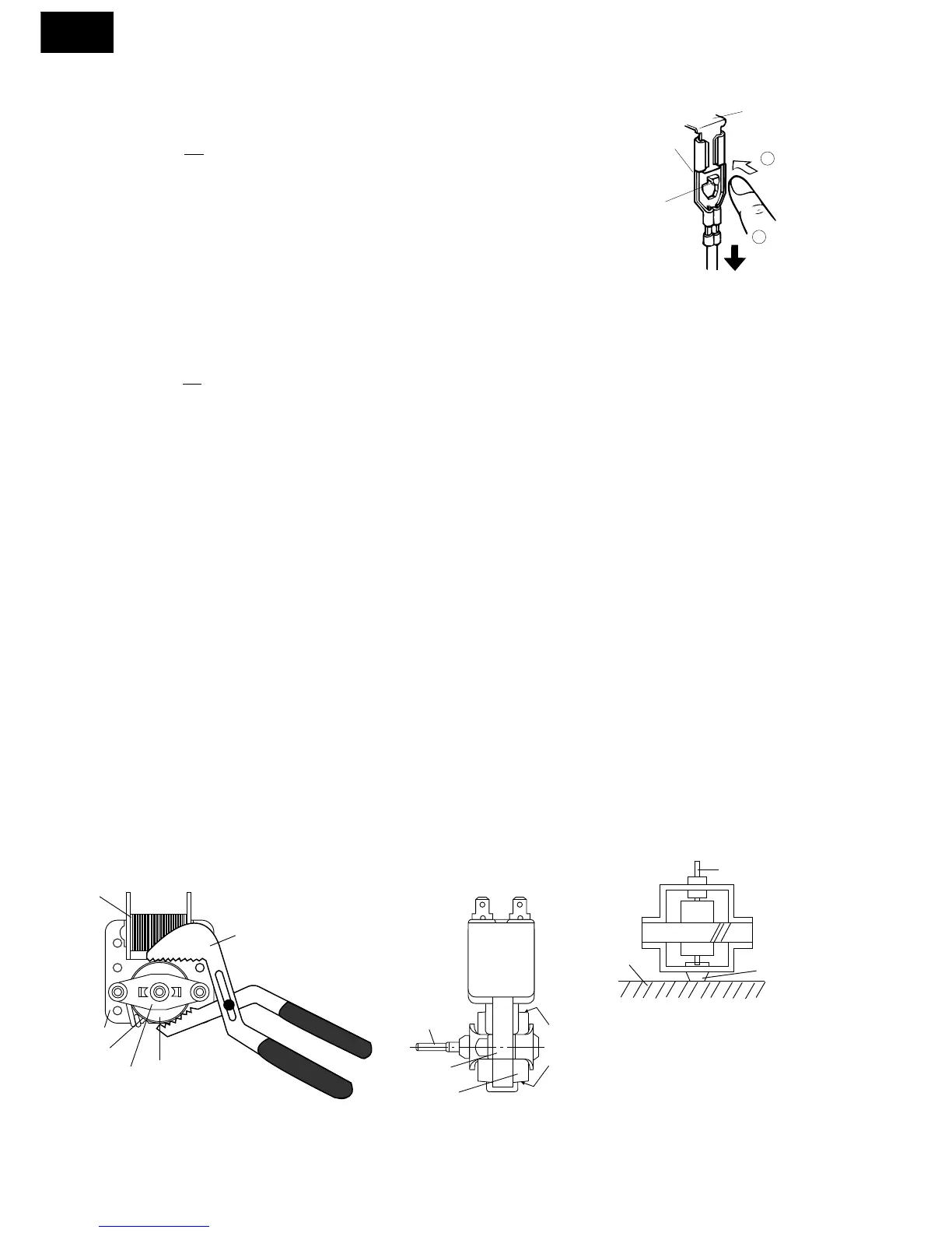
2) Remove the fan blade assembly from the shaft of the fan
motor by pulling fan retainer clip and rotating the fan
blade with your hand.
3) Now, the fan blade will be free.
CAUTION:
* Do not use this removed fan blade again. Because
the hole (for shaft) of it may become bigger than a
standard one.
8. Remove the two (2) screws holding the fan motor to the
fan motor angle.
9. Now, the fan motor is free.
INSTALLATION
1. Install the fan motor to the fan motor angle with the two
(2) screws.
2. Install the fan blade to the fan motor shaft according the
following procedure.
1) Hold the centre of the bracket which supports the shaft
of the fan motor on the flat table.
2) Apply the screw lock tight into the hole (for shaft) of the
fan blade.
3) Install the fan blade to the shaft of fan motor by pushing
the fan blade with a small, light weight, ball peen hammer
or rubber mallet.
CAUTION:
* Do not hit the fan blade strongly when installed because
the bracket may be transformed.
* Make sure that the fan blade rotates smooth after installed.
* Make sure that the axis of the shaft is not slanted.
3. Install the thermal cut-out angle to the fan motor with the
one (1) screw.
4. Install the fan motor angle to the oven cavity with three
(3) screws.
5. Connect the wire leads to the fan motor and the thermal
cut-out, referring to the pictorial diagram.
 Loading...