Do you have a question about the Sharp R-3A56 and is the answer not in the manual?
| Cooking Levels | 10 |
|---|---|
| Voltage | 120V |
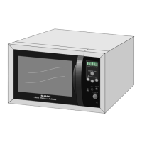
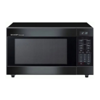
| Category | Microwave Oven |
| Wattage | 1000 Watts |
| Power Output | 1000 Watts |
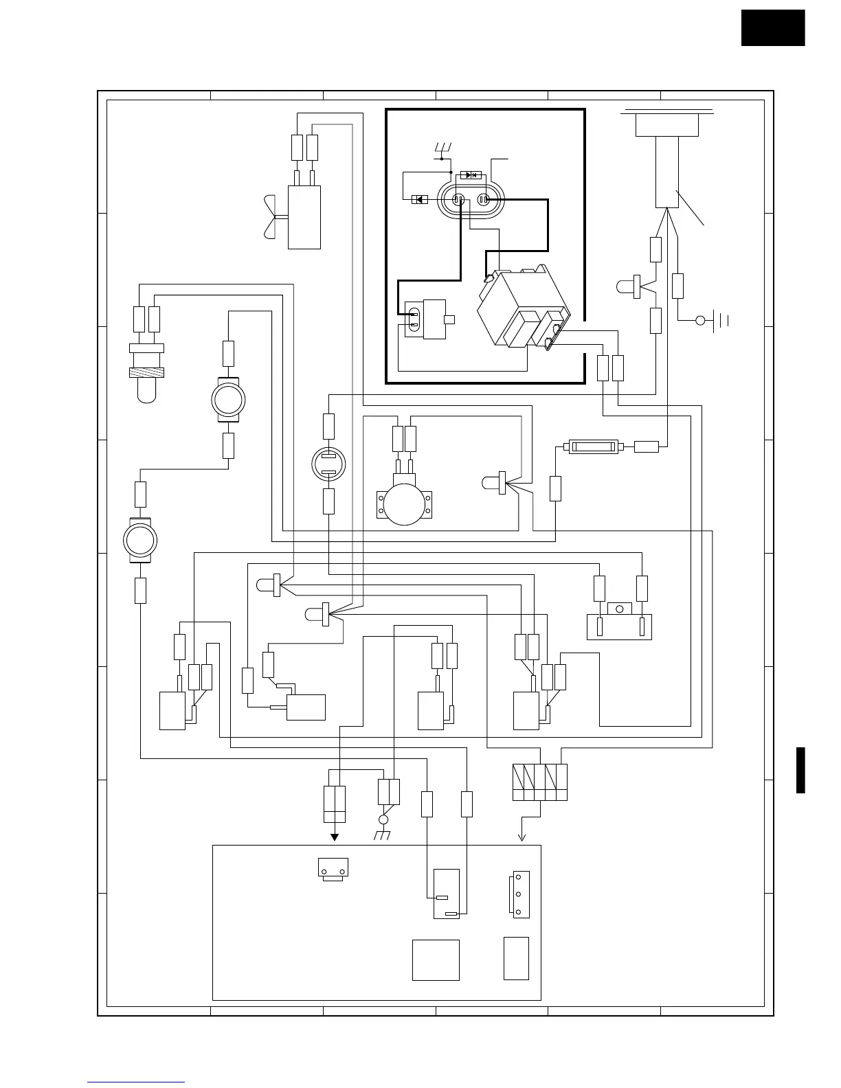
Explains door opening, latch, and monitor switches.
Details fuses, thermal cut-outs, and resistors.
Critical safety warnings and precautions for technicians.
A guide for diagnosing and resolving appliance issues.
Detailed tests for magnetron, output power, transformer, and rectifiers.
Tests for monitor resistor, motors, fuse, and control panel.
Precautions for handling sensitive electronic parts like CMOS LSI.
Safety standards and steps for performing leakage tests.