R -4A52
R-4E52
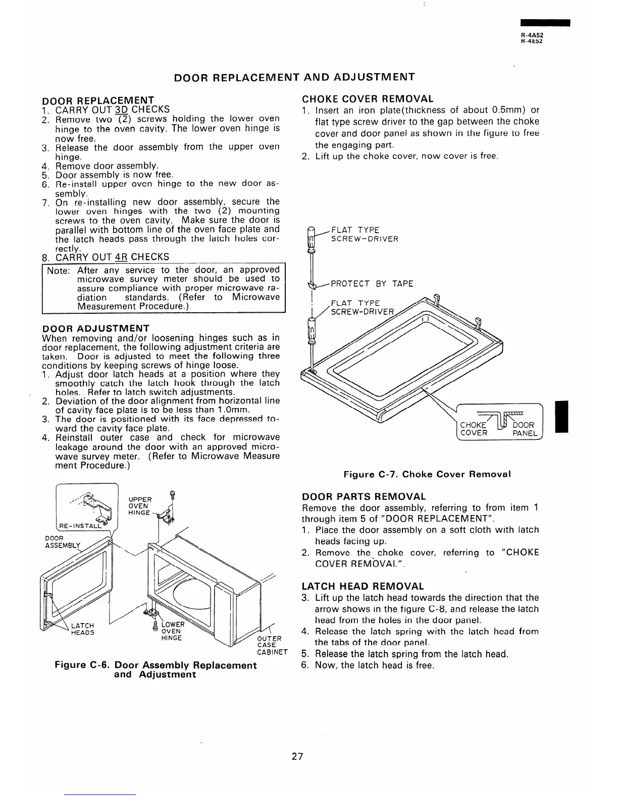
DOOR REPLACEMENT AND ADJUSTMENT
DOOR REPLACEMENT
1. CARRY OUT 3D CHECKS
2. Remove two (2) screws holding the lower oven
hinge to the oven cavity. The lower oven hinge is
now free.
3. ,“z;re the door assembly from the upper oven
4. Remove door assembly.
5. Door assembly is now free.
6. Re-install upper oven hinge to the new door as-
sembly.
7. On re-installing new door assembly, secure the
lower oven hinges with the two (2) mounting
screws to the oven cavity. Make sure the door is
parallel with bottom line of the oven face plate and
the latch heads pass through the latch holes cor-
rectly.
8. CARRY OUT JIFJ CHECKS
Note: After any service to the door, an approved
microwave survey meter should be used to
assure compliance with proper .microwave ra-
diation standards. ( Refer to Microwave
Measurement Procedure.)
DOOR ADJUSTMENT
When removing and/or loosening hinges such as in
door replacement, the following adjustment criteria are
taken.
Door is adjusted to meet the following three
conditions by keeping screws of hinge loose.
1. Adjust door latch heads at a position where they
smoothly catch the latch hook through the latch
1
holes. Refer to latch switch adjustments.
2. Deviation of the door alignment from horizontal line
of cavity face plate is to be less than 1 .Omm.
3. The door is positioned with its face depressed to-
ward the cavity face plate.
4. Reinstall outer case and check for microwave
leakage around the door with an approved micro-
wave survey meter.
(Refer to Microwave Measure
ment Procedure.)
CABINET
Figure C-6. Door Assembly Replacement
and Adjustment
CHOKE COVER REMOVAL
1. Insert an iron plate(thrckness of about 0.5mm) or
flat type screw driver to the gap between the choke
cover and door panel as shown in the figure to free
the engaging part.
2. Lift up the choke cover, now cover is free.
FLAT TYPE
SCREW-DRIVER
PROTECT BY TAPE
FLAT TYPE
SCREW-DRIVE
Figure C-7. Choke Cover Removal
DOOR PARTS REMOVAL
Remove the door assembly, referring to from item 1
through item 5 of “DOOR REPLACEMENT”.
1. Place the door assembly on a soft c,loth with latch
heads facing up.
2. Remove the.* choke cover, referring to “CHOKE
COVER REMOVAL”.
LATCH HEAD REMOVAL
3. Lift up the latch head towards the direction that the
arrow shows in the figure C-8, and release the latch
head from the holes in the door panel.
4. Release the latch spring with the latch head from
the tabs of the door panel.
5. Release the latch spring from the latch head.
6. Now, the latch head is free.
27
 Loading...