R530EWT
11 – 3
[6] OVEN LAMP REMOVAL
1. Disconnect the power supply cord and then remove outer case.
2. Open the oven door and block it open.
3. Discharge high voltage capacitor.
4. Disconnect the wire leads from the oven lamp.
5. Remove the one (1) screw holding the oven lamp to the magnetron
duct.
6. Remove the oven lamp from the magnetron duct.
7. Now, the oven lamp is free.
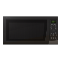
Figure C-1. Oven lamp
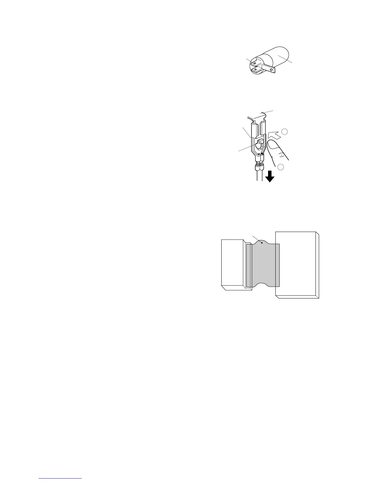
[7] POSITIVE LOCK CONNECTOR (NO-CASE TYPE) REMOVAL
1. Disconnect the power supply cord, and remove outer
case.
2. Open the door and block it open.
3. Discharge high voltage capacitor.
4. Push the lever of positive lock® connector.
5. Pull down on the positive lock® connector.
CAUTION: WHEN CONNECTING THE POSITIVE LOCK®
CONNECTORS TO THE TERMINALS,
INSTALL THE POSITIVE LOCK® SO THAT
THE LEVER FACES YOU
[8] CONTROL PANEL ASSEMBLY REMOVAL
1. Disconnect the power supply cord and then remove outer case.
2. Open the door and block it open.
3. Discharge high voltage capacitor.
4. Disconnect the wire leads from panel components.
5. Remove the one (1) screw holding the control panel assembly to
the oven cavity front plate.
6. Slide the control panel assembly upward and remove it.
7. Now, individual components can be removed.
NOTE: 1) Before attaching a new key unit, wipe off remaining adhe-
sive on the control panel frame surfaces completely with a
soft cloth soaked in alcohol.
2) When attaching the key unit to the control panel frame,
adjust the upper edge and right edge of the key unit to the
correct position of control panel frame.
3) Stick the key unit firmly to the control panel frame by rub-
bing with soft cloth so not to scratch.
1. CPU UNIT
NOTE: Handle the CPU unit carefully so that there is no excessive
force applied to the ribbon connection.
CPU unit
[9] TURNTABLE MOTOR REMOVAL
1. Disconnect the power supply cord.
2. Remove turntable and turntable support from oven cavity.
3. Lay the oven on it's backside. Remove the turntable motor cover by
snipping off the material in four corners.
4. Where the corners have been snipped off bend corner areas flat.
No sharp edges must be evident after removal of the turntable
motor cover.
5. Disconnect wire leads from turntable motor.
(See “Positive lock® connector removal”)
6. Remove one (1) screw holding turntable motor to oven cavity.
7. Now, the turntable motor is free.
8. After replacement use the one (1) screw XOTS740P10000 to fit the
turntable motor cover.
[10] COOLING FAN MOTOR REMOVAL
1. REMOVAL
1. Disconnect the power supply cord and then remove outer case.
2. Open the door and block it open.
3. Discharge high voltage capacitor.
4. Disconnect the wire leads from the fan motor.
5. Remove the two (2) screws holding the fan motor to the oven cavity
back plate.
6. Remove the fan blade from the fan motor shaft according to the fol-
lowing procedure.
7. Hold the edge of the rotor of the fan motor by using a pair of groove
joint pliers.
Oven lamp
Terminal
 Loading...