R530EWT
12 – 1
R530EWT
Service Manual
CHAPTER 12. CIRCUIT DIAGRAMS
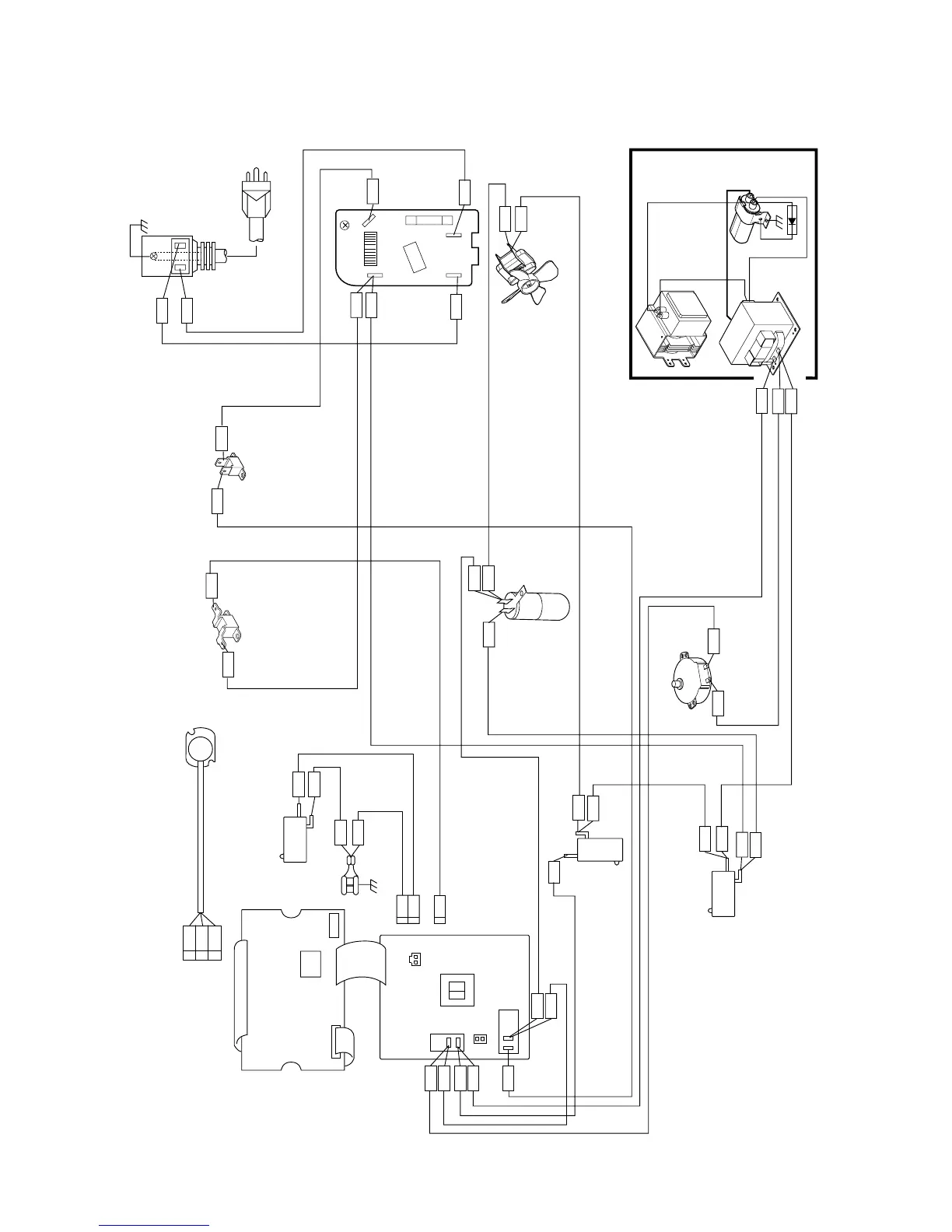
[1] Pictorial Diagram
Figure S-1. Pictorial Diagram
HIGH
VOLTAGE
CAPACITOR
H.V. RECTIFIER
HIGH VOLTAGE COMPONENTS
OVEN LAMP
MAGNETRON
COM.
MONITOR
SWITCH
N.C.
SECONDARY
INTERLOCK
SWITCH
TURNTABLE
MOTOR
POWER
TRANSFORMER
COM.
NO
BLU
RED
GRY
GRY
ORG
WHT
ORG
WHT
BRN
BLU
RED
BLU
BLK
MAGNETRON TEMP FUSE
CAVITY TEMP FUSE
FAN MOTOR
RED
BLK
GRY
ORG
ORG
BLU
WHT
WHT
WHT
POWER SUPPLY
CORD 120V 60Hz
NOTE:
The neutral (WHT) wire must be connected to the
terminal with "N" mark on the power supply cord.
BLK
WHT
GRY
H
N
NOTE:
The grounding conductor of
the power supply cord has
been grounded by power
supply cord fixing screw.
The screw must always be
kept tight.
COM.
N.O.
DOOR
SENSING
SWITCH
PNK
GRN
GRN
to Oven cavity
GRN
PNK
GRN
2
1
CN-B
WHT
1
CN-A
BRN
GRY
RED
WHT
BLK
GRY
WHT
WHT
WHT
SOURCE
LOAD
LOAD
SOURCE
WHT
BLK
AH SENSOR
RED
WHT
1
2
3
CN-F
NOTE: Connect the GRY wire leads to the
cabinet side terminal of the power
transformer to avoid an operation
error of AH sensor.
CN-B
RY2
RY1
PRIMARY
INTERLOCK
RELAY
CN-A
T1
1
1
2
2
CONTROL PANEL
(LSI UNIT)
(POWER UNIT)
CN-F
CN-C
CN-G
 Loading...