Document No. 129-104
Installation Instructions
October 1, 2013
Page 2 of 5 Siemens Industry, Inc.
Mounting Information
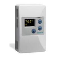
Always mount the room unit vertically.
Locate the room unit:
• according to design specifications and local
regulations.
• where the air circulates around it freely (not in
recessed areas or behind doors).
• allowing a minimum of 4 inches (10 cm) free
space above and below for proper airflow, the
front cover removal tool, and the computer
communication cable.
• away from drafts caused by doors, windows,
outside walls, air registers, pipes, return air
plenums, etc.
• away from heat sources such as strong lights,
fireplaces, direct sunlight, etc.
• on an inside wall (preferably), about 5 feet
(1.5 m) above the finished floor.
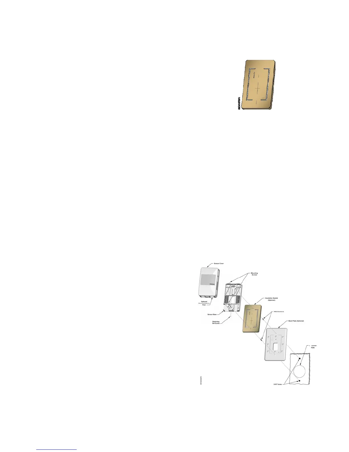
Drywall Mounting (No Rough-in),
Typical
Base Plate Mounting and Wiring
1. Mark the center (cable) hole and the mounting hole
locations, using the room unit base plate as a
template. See
Figure 3.
2. Drill two 3/16-inch (4.8 mm) mounting holes and
mount the two plastic wall anchors flush to below the
wall surface for stable mounting of the device.
3. Cut a 1-inch (25 mm) center hole with a hole saw.
NOTE: It is recommended that you use the
optional Insulating Gasket on the back of
the Sensor Base for hollow wall
installations.
When applying the adhesive-backed
gasket to the back of the Sensor Base,
orient the gasket so that the cut-out
arr
ow portion of the gasket is in the
upper lefthand quadran
t of the Sensor
Base. The Sensor Base has an UP arrow
molded into the surface in the same
quadrant location (see
Figure 6).
Figure 2. Insulating Gasket.
4. Pull about three inches (75 mm) of the cable through
the hole in the base plate.
5. Mount the room unit base plate on the wall, noting
the UP arrow:
NOTE: If required, position the Back Plate
behind the Room Unit Base, aligning the
top and bottom mounting holes, prior to
mounting to the wall:
a. Install the two mounting screws provided, but
do not tighten.
b. Level the room unit base plate for appearance.
c. Tighten the two mounting screws to the room
unit base plate.
6. Cut the cable, leaving about three inches (75 mm)
on the room unit side of the drywall. Ensure that pin
Number 1 connects to the same wire at each end of
the cable.
NOTE: See Figure 2 for details on optional Gasket
application.
Figure 3. Drywall Mounting (No Rough-in), Typical.

 Loading...