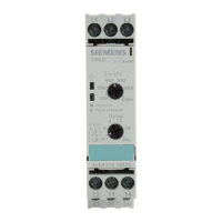
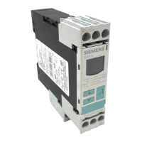
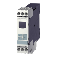
3UG4501 filling level monitoring relay
5.4 Operation
3UG4 / 3RR2 monitoring relays
94 Manual, 05/2016, NEB927043002000/RS-AC/004
The following parameters can be set on the relevant rotary button using a screwdriver:
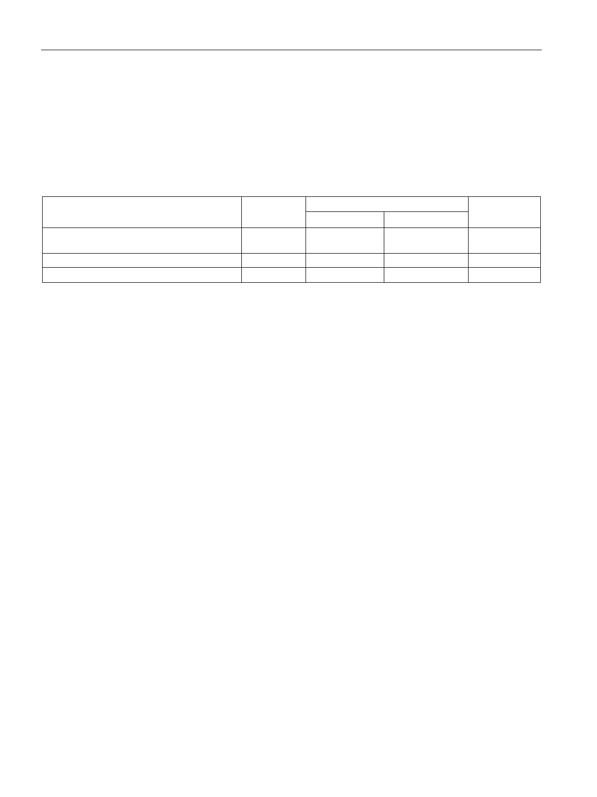
Table 5- 2 Parameter information, 3UG4501 filling level monitoring relay
Monitoring mode
1)
:
drainage control (OV) or inflow control (UN)
3 -- -- --
Sensor sensitivity (R sens)
Tripping delay time (Delay) 5 0.5 s 10 s Continuous
1)
By operating the rotary button, it is possible to choose between drainage control (OV) and
inflow control (UN) depending on the application (one-point control or two-point control).
2)
The position digits refer to the front view in Chapter "Operator controls and connection
terminals (Page 90)."
Chapter "Circuit diagrams (Page 95)" shows the wiring examples for the different monitoring
modes.
The parameters are defined in Chapter "Parameters (Page 363)."
The same screwdriver can be used to set the parameters as for mounting the filling level
monitoring relays.
Depending on the liquid level, the output relay switches in accordance with its set relay
switching behavior (drainage control OV, inflow control UN). If the output relay responds
(contact 11-12 open, contact 11-14 closed), the yellow LED next to the contact symbol on
the device cover lights up.
The switching behavior of the output relay is shown in Chapter "Functions (Page 91)."
 Loading...