5
SETTING THE OPTION
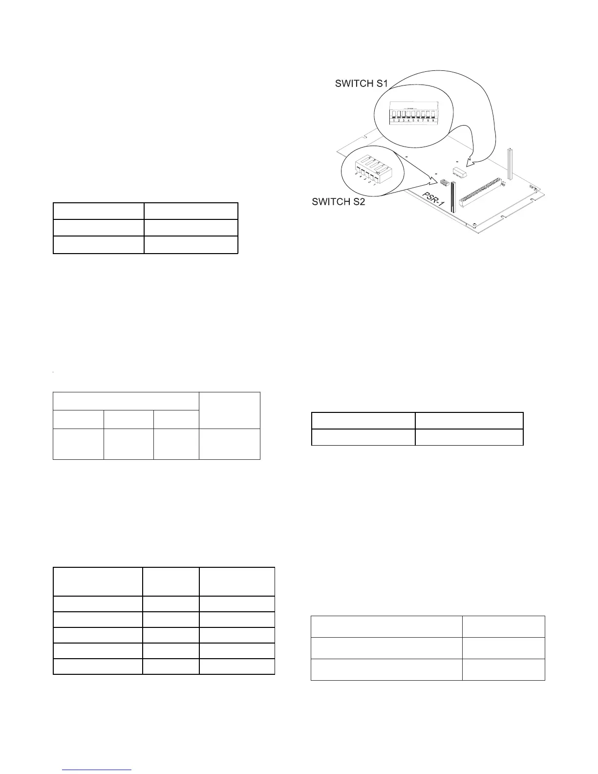
DIPSWITCHES ON SWITCH S2
(See Figure 2)
To Disable the Network (S2-1)
The Disable Network Switch, located at S2-1,
enables or disables the network connection.
DISABLE NETWORK SWITCH SETTINGS
S2-1 Network
Open (or OFF) Enabled
Closed (or ON)
Disabled*
*When not connected to the MXL network
Battery Setting (S2-2, -3, and -4)
There is only one allowable battery switch setting
as shown in the table below. Be sure to set the
PSR-1 battery size in the CSG-M to 31 AH,
regardless of the factory battery size.
SGNITTESHCTIWSYRETTAB
sehctiwSPID
gnigrahC
tnerruC2-2S3-2S4-2S
nepO
)FFOro(
nepO
)FFOro(
desolC
)NOro(
spma0.2
xam
The following table defines the battery voltage
thresholds for the listed battery trouble condi-
tions. These voltages can be viewed in the TEST
POWER menu on the MKB-2 annunciator.
BATTERY VOLTAGE THRESHOLDS
Battery Status Conditions
Battery Voltage
(Volts)
Battery Not Installed <14.0
Charger Disabled <18.3
Battery Low Fault On Battery <21.0
Battery Low Fault On AC <24.0
Battery High Fault >30.0
Security Mode-UL 1076 Operation (S2-5)
To Disable the Tamper Switch
The PSR-1 does not support the use of security
points from initiating circuits in its enclosure. To
disable the tamper switch input of the PSR-1, set
the security mode to disabled.
The Disable Security Mode switch is located at S2-5.
DISABLE SECURITY MODE SWITCH SETTINGS
S2-5 UL1076
Open (or OFF) Disabled
Input Power Specifications
MPS-6
Input Voltage: 120VAC, +10%, -15%
Input Current: 2A max
MPS-12
Input Voltage: 120 VAC, +10%, -15%
Input Current: 4A max
ELECTRICAL RATINGS
Figure 2
Switches S1 and S2 on the PSR-1
tnerruCeludoMCDV5evitcAAm0
*tnerruCeludoMCDV42evitcAAm511
tnerruCeludoMCDV42ybdnatSAm09
rosecivedybnwardtne
rrucynaedulcnitonseoD*
.1-RSPehtybderewopseludom
 Loading...