9
Figure 8
CZM-1 Power, Class B Wiring
REFER TO WIRING SPECIFICATION FOR MXL, MXL-IQ
AND MXLV SYSTEMS, P/N 315-092772 REVISION 6 OR
HIGHER, FOR FURTHER INFORMATION.
+
_
CZM-1
CZM-1
CZM-1
T-TAPPING ALLOWED
6
5
4
2
3
1
TB3
CLASS B WIRING
18-31 VDC
2A MAX
POWER LIMITED TO
NFPA 70 PER NEC 760
4 OHMS MAX PER PAIR (TOTAL)
18 AWG MIN
POSITIVE AND NEGATIVE
GROUND FAULT DETECTED
AT <30K OHMS FOR TB3, 1-6
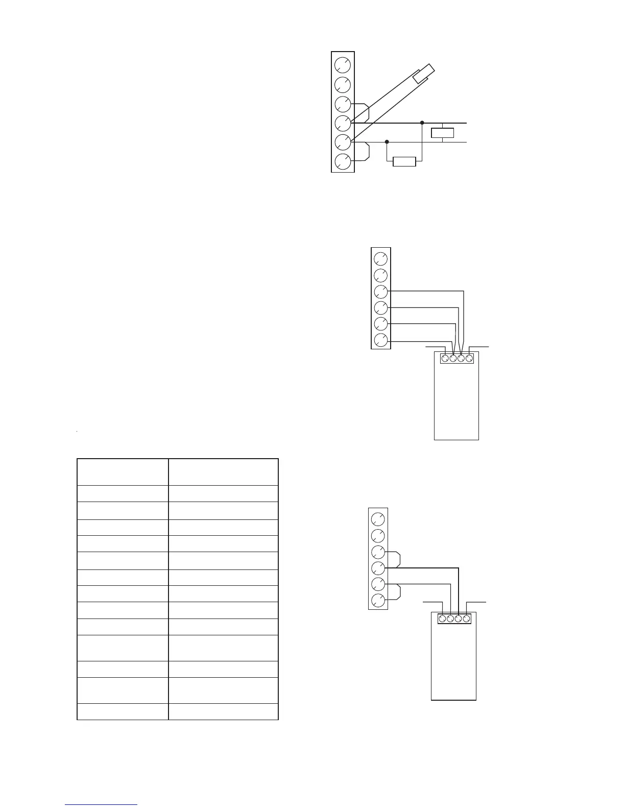
Figure 9
PS-5A Power, Class A Wiring
REFER TO WIRING SPECIFICATION FOR MXL, MXL-IQ
AND MXLV SYSTEMS, P/N 315-092772 REVISION 6 OR
HIGHER, FOR FURTHER INFORMATION.
4321
18-31 VDC
2A MAX
POWER LIMITED TO
NFPA 70 PER NEC 760
4 OHMS MAX PER
PAIR (TOTAL)
18 AWG MIN
+
+
_
_
6
5
4
2
3
1
TB3
PSR-1
PS-5A
DO NOT
USE
DO NOT
USE
_
+
POSITIVE AND NEGATIVE GROUND FAULT
DETECTED AT <30K OHMS FOR TB3, 1-6
Figure 10
PS-5A Power, Class B Wiring
REFER TO WIRING SPECIFICATION FOR MXL, MXL-IQ
AND MXLV SYSTEMS, P/N 315-092772 REVISION 6 OR
HIGHER, FOR FURTHER INFORMATION.
+
_
6
5
4
4321
2
3
1
TB3
PSR-1
PS-5A
18-31 VDC
2A MAX
POWER LIMITED TO
NFPA 70 PER NEC 760
4 OHMS MAX PER
PAIR (TOTAL)
18 AWG MIN
DO NOT
USE
DO NOT
USE
_
+
POSITIVE AND NEGATIVE GROUND FAULT
DETECTED AT <30K OHMS FOR TB3, 1-6
20 CZM-1s, 4 ohms max. Multiple Class B
power connections can be used if you do not
exceed the ratings above (40 CZM-1s max
and 4 ohms per run max). For example, you
could have four individual Class B power runs,
for a total of 40 devices (for example, 12, 8, 6,
and 14 CZM-1s), with each of the four runs not
exceeding 4 ohms resistance.
T-tapping is allowed, provided the total resis-
tance of all wires does not exceed 4 ohms.
6. Refer to Figures 9 and 10 for wiring instruc-
tions for the PS-5A.
MOI-7 Power (P9)
The PSR-1 may be used in standalone mode as
the power supply for the MOI-7. In this configura-
tion the MOI-7 and the PSR-1 must be in the
same enclosure. A separate 5V output is provided
for the MOI-7. The PSR-1 local trouble contact
must also be connected as a means of reporting
PSR-1 troubles to the MXL. See Figure 11 for the
wiring diagram.
See Figure 12 if the MOI-7 is in a separate enclo-
sure. In this configuration do not use the 5V
power on P9. A separate PS-5A must be in-
cluded
in the remote enclosure with the MOI-7.
REWOPV42YRAILIXUA
SECIVEDELBITAPMOC
seciveDelbitapmoC
noitallatsnI
snoitcurtsnI
6B1-MZC7-553590-513N/P
6B-PC
I8-603590-513N/P
61-DOM7-038090-513N/P
7-IOM7-997290-513N/P
A5-SP8-763290-513N/P
7N5-SP21-927290-513N/P
C5-/5-B
KM3-727840-513N/P
C6-/6-BKM4-227840-513N/P
CF3-/C-/F3-/3-CCR5-566840-513N/P
thginKtneliS
9215/8215
5-492390-5
13N/P
53-RS8-196780-513N/P
D4-/D3-/D2-HDS
D8-/D7-/D6-/D5-/
3-184940-513N/P
1-SN
§
3-904580-513N/P
§
noitidEht8468LUrepdetsiL
 Loading...