6/6
Siemens Building Technologies Room sensors QFA20… CE1N1857en
HVAC Products 06.06.2005
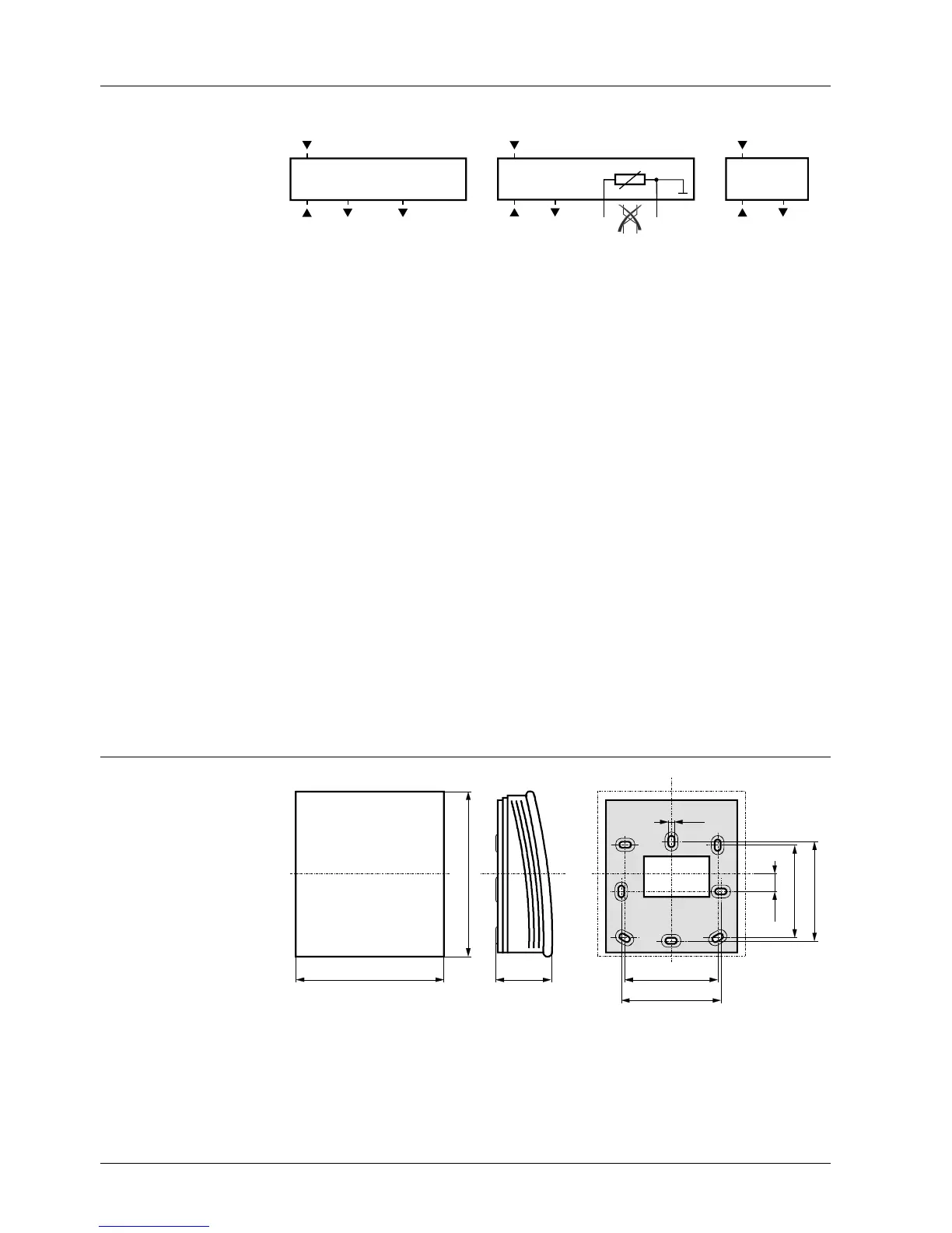
Internal diagram
QFA2060 QFA2020,
QFA2040 (serie B or higher)
QFA2000
G0
U1 U2
G
1857G01
r.h.
R1 = −35...+35 °C /
R2 = 0...50 °C
G0
U1 BS
G
1857G02
r.h.
MS
G0
U1
G
1857G03
r.h.
G, G0 Operating voltage AC 24 V (SELV) or DC 13.5...35 V
U1 Signal output DC 0...10 V for relative humidity 0...100 %
U2 Signal output DC 0...10 V for temperature range 0...50 °C (R2 = factory setting)
or − 35...+35 °C
BS, MS Signal output LG-Ni 1000 oder T1 (passive, simulated) for temperature range 0…50 °C;
the wires must not be interchanged
Dimensions
90
100
36
4,2
9,5
56
60
56
60
1857M01
Drilling plan
Dimension in mm

 Loading...