28 / 62
Siemens RDF302 Basic documentation CE1P3079en
Smart Infrastructure 2022-06-17
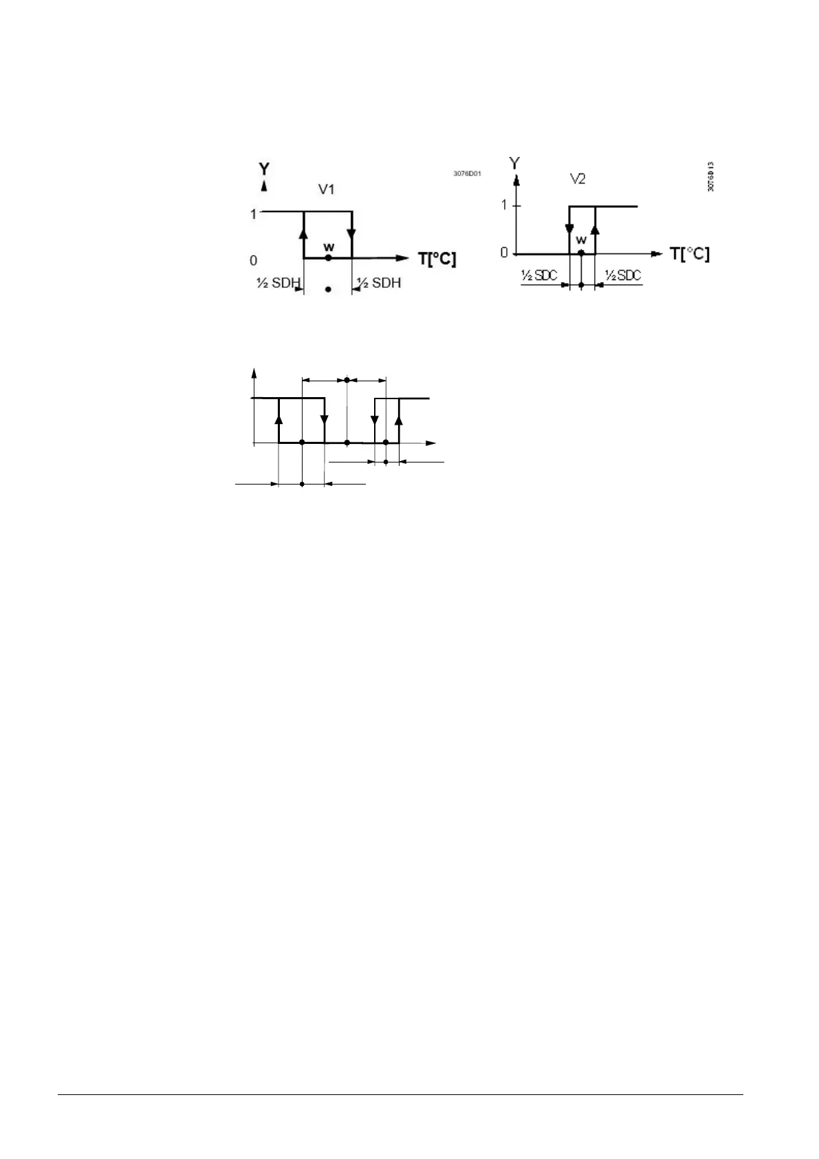
The diagrams below show the control sequence for 2-position control.
Heating mode with manual selection
(P01=2) or
for P09 >= P10 in heating sequence *)
Cooling mode with manual selection
(P01=2) or
for P09 >= P10 in cooling sequence *)
Heating and cooling mode (P01 = 04)
Y
½ SDC
1
0
½ SDC
w
3076D11
T[°C]
V2
½ SDH ½ SDH
V1
½ x
dz
½ x
dz
w Room temperature setpoint
V1 Control command “Valve” or “Comp.” (H)
V2 Control command “Valve” or “Comp.” (C)
SDH Switching differential “Heating” (P30)
SDC Switching differential “Cooling” (P31)
The diagrams only show the PI thermostat’s proportional part.
Setting the sequence and the control outputs
Refer to sections 3.4 "Applications", 3.6.1 "Sequences", and 3.7 "Outputs".

 Loading...