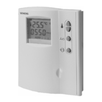
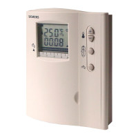
Technical Instructions RDF30U Room Temperature Controller with LCD
Document Number 155-335 for Four-Pipe Fan Coil Units
September 27, 2007
Page 2 Siemens Industry, Inc.
ARG70 Adapter plate for 4-inch × 4-inch or 2-inch × 4-inch conduit boxes
141-570 Lockable thermostat guard
QAH11.1 Changeover/remote temperature sensor
Warning/Caution
Notations
Personal injury or loss of life may occur if you do not perform
a procedure as specified.
Equipment damage may occur if you do not follow a
procedure as specified.
The controller acquires the room temperature via its integrated sensor or optional
external return air temperature sensor (QAH11.1) and maintains the setpoint by
delivering two-position valve control output commands.
The switching differential is 2 K (3.6F) in Heating mode (adjustable in Parameter 10)
and 1 K (1.8F) in Cooling mode (adjustable in Parameter 11).
The fan is switched to the selected speed via control output 12, 11 or 10.
When the “Temperature-dependent fan control“ function is activated (can be selected
with DIP Switch No. 1), the fan is switched on/off depending on the temperature,
together with the valve. It is switched off when any of the following occurs:
• leaving the heating or cooling sequence, provided the “Temperature-dependent fan
control“ function is activated.
• manually changing to Standby provided no setpoints (example, for freeze
protection) are set and active.
• activating an external operating mode changeover switch, provided application
conditions do not call for Economy mode.
• turning off the controller’s power supply.
If DIP Switch No. 2 is set to ON (factory setting), the controller displays the measured
room or return air temperature (unless parameters or setpoints are temporarily
changed). If the DIP switch is set to OFF, the controller displays the Normal operating
mode setpoint. In this case, the value of the current temperature reading can only be
visualized temporarily by selecting Parameter P14.
Water-based Fan Coil
Application (Heating
mode)
When used in connection with four-pipe fan coils set DIP Switch No. 4 to ON.
Use in conjunction with two valves, for heating and cooling operation.
Terminals 4 and 2 (neutral) or 5 and 2 command the control valve.
Output terminals 4 and 2 are closed (24 Vac) when:
1. the measured room temperature is half the switching differential below the setpoint
(W, Heating mode), and
2. the valve has been closed for more than one minute (Parameter P20).
Output terminals 4 and 2 are open (0 Vac) when:
1. the measured room temperature is half the switching differential above the setpoint
(W, Heating mode), and
 Loading...