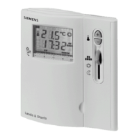
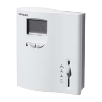
Technical Instructions RDF30U Room Temperature Controller with LCD
Document Number 155-335 for Four-Pipe Fan Coil Units
September 27, 2007
Page 8 Siemens Industry, Inc.
Mounting,
Installation and
Commissioning
Notes, Continued
▪ Prior to installing the changeover sensor, thermal conductive paste must be applied
to the location on the pipe where the sensor is placed.
▪ Installation Instructions are included with the controller.
WARNING:
• Sensor inputs 7, 8, and 9 carry live voltage potential. If the sensor’s
cables must be extended, the cables used must be suited for live
voltage.
• The cables used must meet the insulation requirements for live
voltage.
If the room temperature displayed by the controller is inconsistent with the room
temperature being measured, the temperature sensor of the RDF30U can be
recalibrated. To recalibrate, change Parameter P09.
Specifications
Power Supply
Operating voltage 24 Vac, +20/-25%
Frequency 50/60 Hz
Power consumption 6 VA maximum
Fan control outputs 12, 11, 10 24 Vac
Rating 5 (3) A maximum
Valve control output 4, 6 (NO) 24 Vac
55 (3) A maximum
Return air temperature sensor QAH11.1 safety class II
status input 9-8 NTC resistor 3 k at 77°F (25°C)
Status input D1 and GND
Contact sensing SELV 6 to 15 Vdc/3 to 6 mA
Insulation against live voltage 4 kV, reinforced insulation
Operating action Selectable
Permissible cable length with copper 262 ft (80 m)
cable 14 AWG for connection to terminals
7, 8, 9 and D1, GND
Setpoint setting range 41°F to 95°F (5°C to 35°C)
Control deviation at 77°F (25°C) + 0.5 K (1°F) maximum
Switching differential in Heating mode, 2 K (3.6°F)
adjustable
Switching differential in Cooling mode, 1 K (1.8°F)
adjustable
Dead zone X
dz
in Normal mode (adjustable) 2 K (3.6°F)
Setpoint, Economy mode , heating, 61°F (16°C)
adjustable
Setpoint, Economy mode , cooling, 82°F (28°C)
adjustable
Setpoint, Standby , heating, adjustable 46°F (8°C)
Setpoint, Standby , cooling, adjustable OFF
 Loading...