11/14
Siemens Flush-mounted Room Thermostat CB1N3066en
Smart Infrastructure 2019-10-25
Connection terminals solid wires or prepared
stranded wires
2
*) The documents can be downloaded from http://siemens.com/bt/download.
1)
No condensation is allowed.
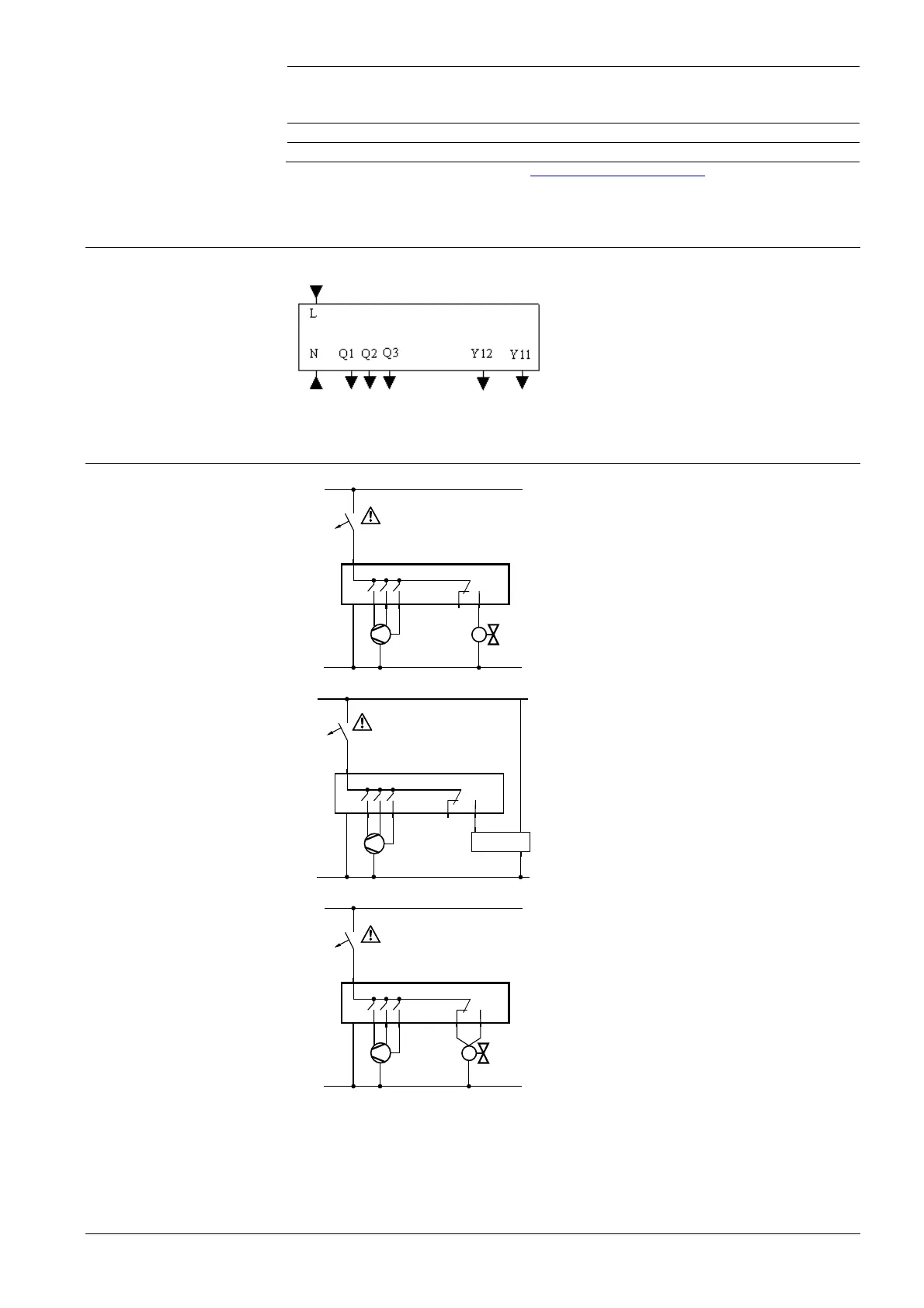
Connection terminals
L, N Operating voltage AC 230 V
Q1 Control output “Fan speed 1 AC 230 V
Q2 Control output “Fan speed 2 AC 230 V
Q3 Control output “Fan speed 3 AC 230 V
Y11 Control output “Valve” AC 230 V (N.O.)
Y12 Control output “Valve” AC 230 V (N.C.)
Connection diagrams
L
N
L
N Y12
Y11
AC 230 V
N1
M1
V1
4(2)A
Max.
4(2)A
Max.
Q1 Q2 Q3
max. 10 A
N1 RDF310.2/MM
V1 On/off valve AC 230 V
M1 3-speed fan
L
N
L
N Y12
Y11
AC 230 V
N1
M1
4(2)A
Max.
4(2)A
Max.
Q1 Q2 Q3
Y
L
NV2
max. 10 A
N1 RDF310.2/MM
V2 Electromotoric actuator, e.g. SUA21/1
M1 3-speed fan
L
N
L
N Y12
Y11
AC 230 V
N1
M1
V3
4(2)A
Max.
4(2)A
Max.
Q1 Q2 Q3
max. 10 A
N1 RDF310.2/MM
V3 3-wire on/off (SPDT) zone valve
M1 3-speed fan
 Loading...