12 / 13
Siemens Room temperature controller REV17.. CE1N2203en
Building Technologies 24.04.2008
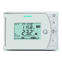
Connection diagrams
L
L1
Y1
M1
N1
A
C
2
4
.
.
.
2
5
0
V
2
2
5
2
A
0
2
N
S1
T1 T2
L2
L
N
DC 3 V
REV17 / REV17DC
L Phase, AC 24 … 250 V
S1
Remote control unit (potential-free)
L1
N.O. contact,
AC 24 …250 V / 6 (2.5) A
T1
Remote control signal
L2
N.C. contact,
AC 24 … 250 V / 6 (2.5) A
T2 Remote control signal
M1
Circulating pump
Y1
Actuating device
N1
REV17… controller
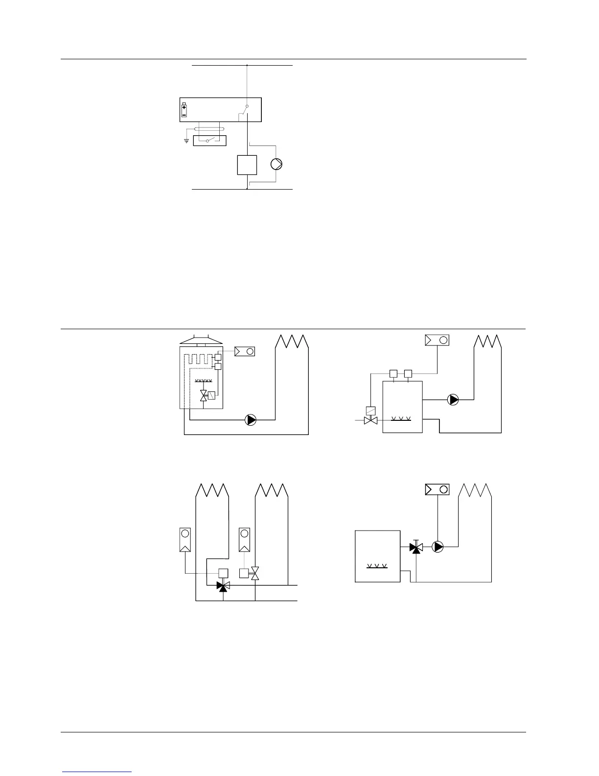
Application examples
T
T
F1
F2
N1
M1
Y2
2252S01
T
T
F1
F2
N1
M1
Y2
2252S02
T T
Instantaneous water heater Atmospheric gas burner
N1
Y4
2252S03
N1
Y3
T T
T
N1
Y1
2252 S04
M1
Zone valve Circulating pump with precontrol by
manual mixing valve
F1
Thermal reset limit thermostat Y1 3-port valve with manual adjustment
F2
Manual reset safety limit thermostat Y2 Magnetic valve
M1 Circulating pump Y3 Three-port valve with actuator
N1 REV17.. room temperature controller Y4 Two-port valve with actuator
 Loading...