Introduction
1.2Description
• CSA/UL 62368-1 safety approved to 85 °C (185 °F)
1.2 Description
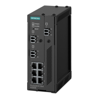
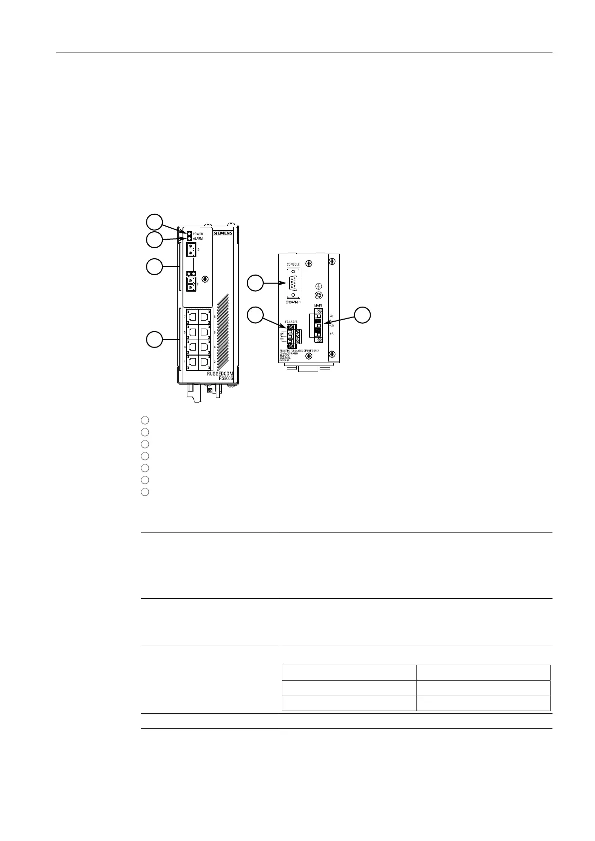
The RUGGEDCOM RS900G features various ports, controls and indicator LEDs on the
front panel for connecting, configuring and troubleshooting the device.
1
ALARM LED
2
POWER LED
3
Fiber Optic or SFP (Small Form-Factor Pluggable) Ethernet Ports
4
Copper Ethernet Ports
5
RS-232 Console Port (DB9)
6
Failsafe Alarm Relay
7
Power Supply Terminal Block
Figure1.1 RUGGEDCOM RS900G
Communication Ports Receive and transmit network traffic, as well as provide remote Web
access to the RUGGEDCOM RS900G operating system. For more
information, refer to:
• "Connecting to the Device (Page 17)"
• "Communication Ports (Page 19)"
RS-232 Console Port The serial console port is for interfacing directly with the device
and accessing initial management functions. For information
about connecting to the device via the serial console port, refer to
"Connecting to the Device (Page 17)".
POWER LED Illuminates when power is being supplied to the device.
Color Description
Green Device is receiving power
Off No power
ALARM LED Illuminates when an alarm condition exists.
2
RUGGEDCOM RS900G
Installation Manual, 01/2021, C79000-G8976-1025-08
 Loading...