RUGGEDCOM RS910
Installation Guide
Chapter 1
Introduction
Description 3
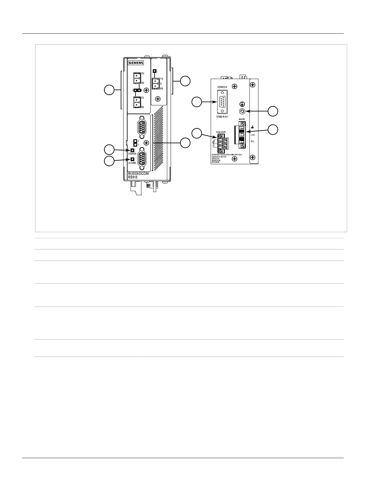
Figure1: RUGGEDCOM RS910
1.POWER LED 2.ALARM LED 3.[Optional] Copper (10/100Base-TX) or Fiber Optic (100Base-FX) Ethernet Ports 4.Serial Ports
5.RS232 Console Port (Serial) 6.Failsafe Alarm Relay 7.Chassis Ground Connection 8.Power Supply Terminal Block
POWER LED Illuminates when power is supplied to the device.
ALARM LED Illuminates when an alarm condition exists.
RS232 Console Port The serial console port is for interfacing directly with the device and accessing initial
management functions. For information about connecting to the device via the serial
console port, refer to Section2.5, “Connecting to the Device” .
Communication Ports Receive and transmit data, as well as provide access to the RUGGEDCOM ROS Web interface.
For more information about the various ports available for the RUGGEDCOM RS910, refer to
Chapter3, Communication Ports .
Failsafe Alarm Relay Latches to default state when a power disruption or other alarm condition occurs. For more
information, refer to:
• Section2.4, “Connecting the Failsafe Alarm Relay”
• Section4.2, “Failsafe Relay Specifications”
Power Supply Terminal Block A pluggable terminal block. For more information, refer to Section2.3, “Connecting Power”
and Section4.1, “Power Supply Specifications” .
 Loading...