RUGGEDCOM RS910
Installation Guide
Chapter 3
Communication Ports
Connecting Multiple RS485 Devices 19
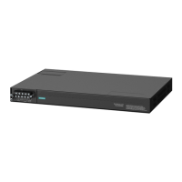
Figure17:Serial RJ-45 Port
Pin
f
RS232 Mode RS485 Mode RS422 Mode
1
g
DSR/RI RX-
2
g
DCD
3
h
DTR
4 Common (Isolated) Ground
5 RX RX+
6 TX TX/RX+ TX+
7
h
CTS
i
8
h
RTS
i
TX/RX- TX-
Shield Chassis Ground
f
No internal termination is provided.
g
Connected internally.
h
Connected internally.
i
In RS232 mode, this pin enters a high impedance state. A DTE that asserts RTS will see CTS asserted, although the device will not perform hardware flow control.
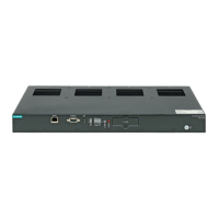
Figure18:Serial ST Fiber Port
1.Rx Connector 2.Tx Connector
More Information
For specifications on serial ports, refer to Section4.5, “Serial Port Specifications” .
For information about how to connect devices configured to run in RS485 mode, refer to Section3.4, “Connecting
Multiple RS485 Devices” .
Section3.4
Connecting Multiple RS485 Devices
Each RS485 port can communicate with multiple RS485 devices by wiring devices together in sequence over a
single twisted pair with transmit and receive signals on the same two wires (half duplex). For reliable, continuous
communication, adhere to the following guidelines:
• To minimize the effects of ambient electrical noise, use shielded cabling.
• The correct polarity must be observed throughout a single sequence or ring.
• The number of devices wired should not exceed 32, and total distance should be less than 1219 m (4000 ft) at
100 kbps.
• The Common terminals should be connected to the common wire inside the shield.
 Loading...